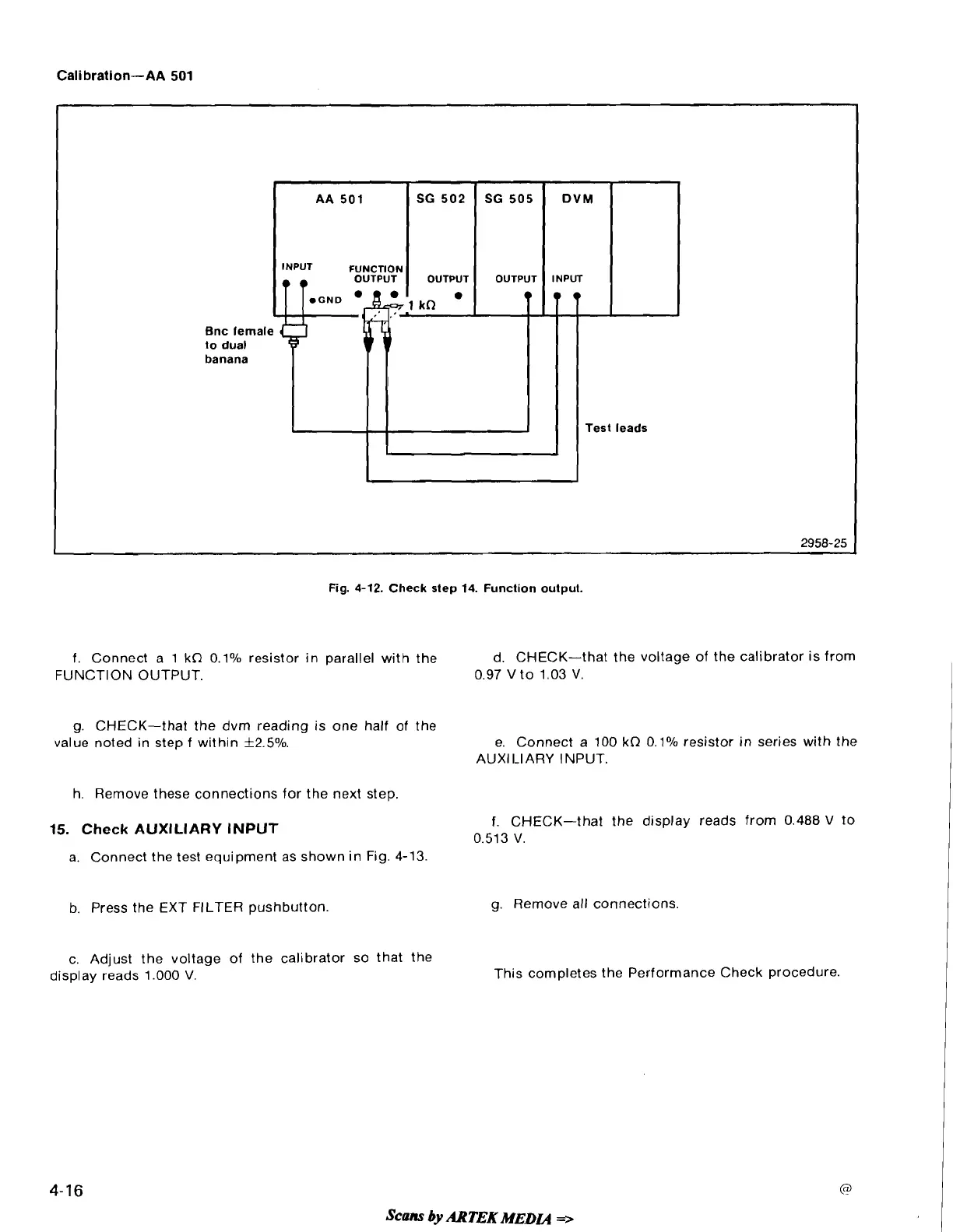
Fig.
4-12.
Check step
14.
Function output.
f. Connect a 1 kQ 0.1% resistor in parallel with the
d. CHECK-that the voltage of the calibrator is from
FUNCTION OUTPUT.
0.97 Vto 1.03 V.
g.
CHECK-that the dvm reading is one half of the
value noted in step f within
f
2.5%.
e. Connect a 100
kQ
0.1% resistor in series with the
AUXl I-IARY INPUT.
h. Remove these connections for the next step.
15.
Check
AUXILIARY INPUT
f.
CHECK-that the display reads from 0.488 V to
0.513 V.
a. Connect the test equipment as shown in Fig. 4-13.
b.
Press the EXT FILTER pushbutton.
g. Remove all connections.
c. Adjust the voltage of the calibrator so that the
display reads 1.000
V.
This completes the Performance Check procedure.
Scans
by
ARTEK
MEDCQ
=>
 Loading...


