Cali bration-AA
501
d.
Connect the test dvm set to read 0.0 mV to TP1310.
h. Remove the shorting bar for the next step.
e.
ADJUST-R1320, Dist Amp Offset, for 0.0 mV
+I
mV on the dvm.
3.
Adjust Volts and Avg Cal
f. Leave the shorting bar for the next step.
2.
Adjust Rms and Avg Zero
a. Make certain the FUNCTION LEVEL and VOLTS
pushbuttons are pressed.
a. Make certain the INPUT is shorted. See Fig. 4-14.
b. Make certain the INPUT LEVEL RANGE is set to the
2 V position.
b. Make certain the FUNCTION LEVEL and VOLTS
pushbuttons are pressed. c. Press the RESPONSE pushbutton.
c. Set the INPUT LEVEL RANGE switch to the 2 V
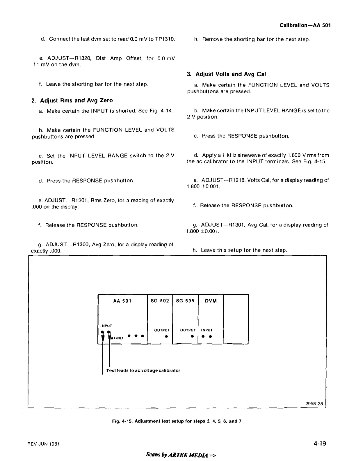
d. Apply a 1 kHz
sinewave of exactly 1.800 V rms from
position.
the ac calibrator to the INPUT terminals. See Fig. 4-15.
d. Press the RESPONSE pushbutton.
e.
ADJUST-R1218, Volts Cal, for a display reading of
1.800
0.001,
e. ADJUST-R1201, Rms Zero, for a reading of exactly
.000 on the display. f. Release the RESPONSE pushbutton.
f. Release the RESPONSE pushbutton.
g.
ADJUST-R1301, Avg Cal, for a display reading of
1.800
kO.001.
g. ADJUST-R1300, Avg Zero, for a display reading of
exactlv
.000. h. Leave this setup for the next step.
AA
501 SG 502
SG
505
DVM
INPUT
OUTPUT OUTPUT
INPUT
a
a.
1
Test leads toac voltagecalibrator
Fig.
4-15.
Adjustment test setup for steps
3,
4,
5,
6,
and
7.
REV
JUN
1981
Scam
by
ARTEK
MEDLA
 Loading...


