Theory of Operatlon-AA
501
frequencies below about 10 kHz. Below about 1 kHz
K1231 is also activated, while below about 100 Hz K1230,
K1231, and K1232 are used. K1030 is energized in the
upper half of each decade reducing resistances by afactor
of three and scaling up frequency by three. Continuous
tuning within each half decade is achieved by adjusting
the impedance of an electronic resistor
(U1131)
with LDR
opto isolators
U1031 and U1032. As the LDR resistance
rises, the electronic resistor value decreases, at the
junction of
U1031 and R1132, raising the filter frequency.
Minor variations in the gain of the band pass filter (which
would cause incomplete cancellation of the fundamental)
are compensated by a third LDR,
U1030. Drive signalsfor
the
LDRs come from the control loop circuitry.
Synchronization signals to run the control loops come
from the outputs of
U1130 and U1120A.
Frequency Band Discriminator
0
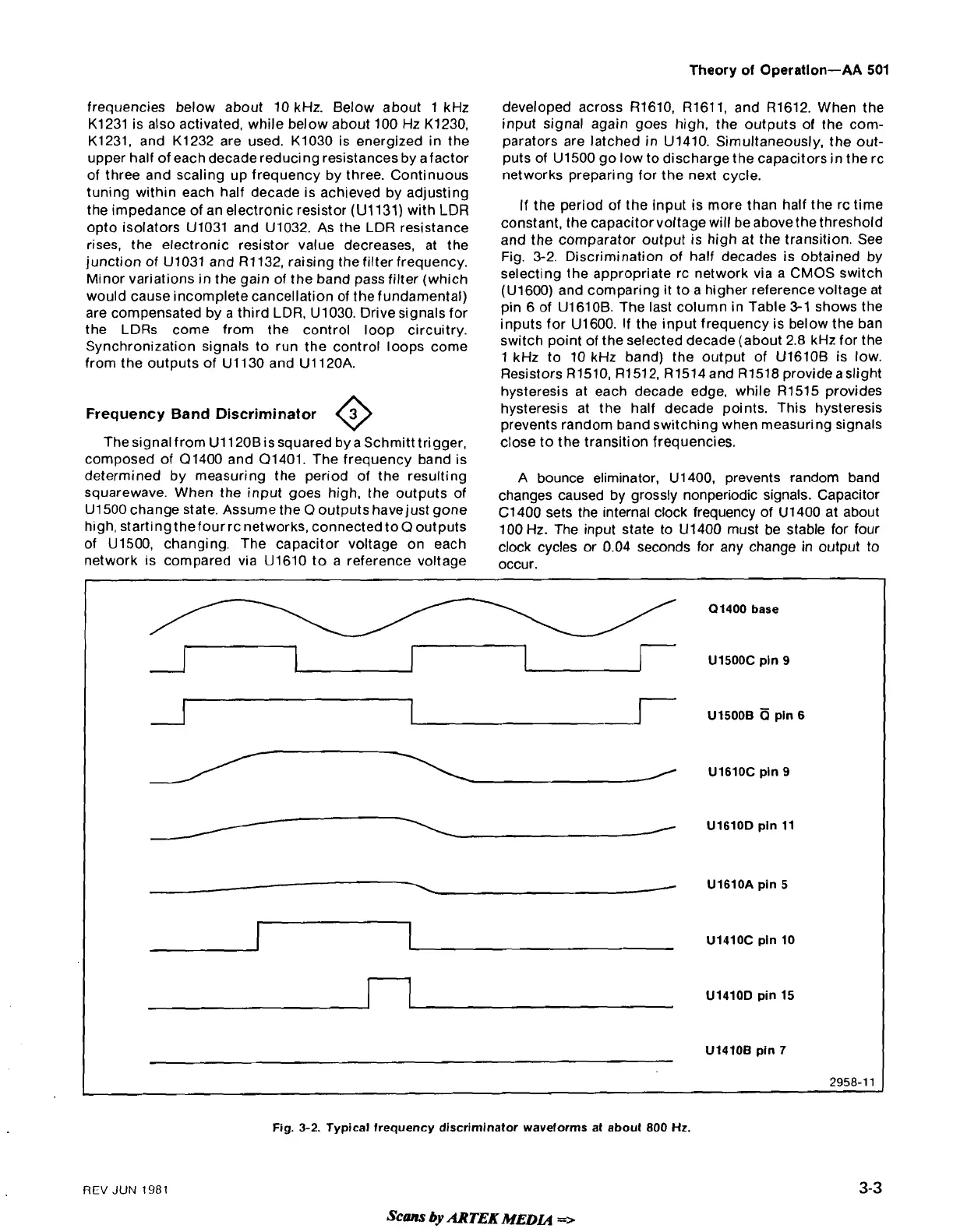
The signal from Ul120Bis squared by a Schmitt trigger,
composed of
Q1400 and Q1401. The frequency band is
determined by measuring the period of the resulting
squarewave. When the input goes high, the outputs of
U1500 change state. Assume the O outputs havejust gone
high, startingthefourrc networks, connected
to0 outputs
of
U1500, changing. The capacitor voltage on each
network is compared via
U1610 to a reference voltage
developed across
R1610, R1611, and R1612. When the
input signal again goes high, the outputs of the com-
parators are latched in
U1410. Simultaneously, the out-
puts of
U1500 go low to discharge the capacitors in the rc
networks preparing for the next cycle.
If the period of the input is more than half the
rc time
constant, the capacitorvoltage will be
abovethe threshold
and the comparator output is high at the transition. See
Fig. 3-2. Discrimination of half decades is obtained by
selecting the appropriate rc network via a
CMOS
switch
(U1600) and comparing it to a higher referencevoltage at
pin 6 of
U1610B. The last column in Table
3-1
shows the
inputs for
U1600. If the input frequency is below the ban
switch point of the selected decade (about 2.8 kHz for the
1 kHz to 10 kHz band) the output of
U1610B is low.
Resistors
R1510, R1512. R1514and R1518 provideaslight
hysteresis at each decade edge, while
R1515 provides
hysteresis at the half decade points. This hysteresis
prevents random band switching when measuring signals
close to the transition frequencies.
A bounce eliminator,
U1400, prevents random band
changes caused by grossly nonperiodic signals. Capacitor
C1400 sets the internal clock frequency of U1400 at about
100 Hz. The input state to
U1400 must be stable for four
clock cycles or 0.04 seconds for any change in output to
occur.
01400 base
A--1
71
r
U1500C pin
9
1
UlsOOB6pln6
6
U1610C pin
9
/
U1610D pin 11
-
U1610A pin 5
Ul4lOC pln 10
UlrlOD pin 15
U1410B pin
7
2958-1
1
REV
JUN
1981
Fig.
3-2.
Typical frequency discriminator waveforms at about 800
Hz.
scm
by
ARTEK
MEDa
=>
 Loading...


