AA
501 SG 502 SG 505
DVM
INPUT
OUTPUT
OUTPUT
INPUT
T
.
..
Dual banana
to bnc female
adapter
1
I
I
Coaxial cable
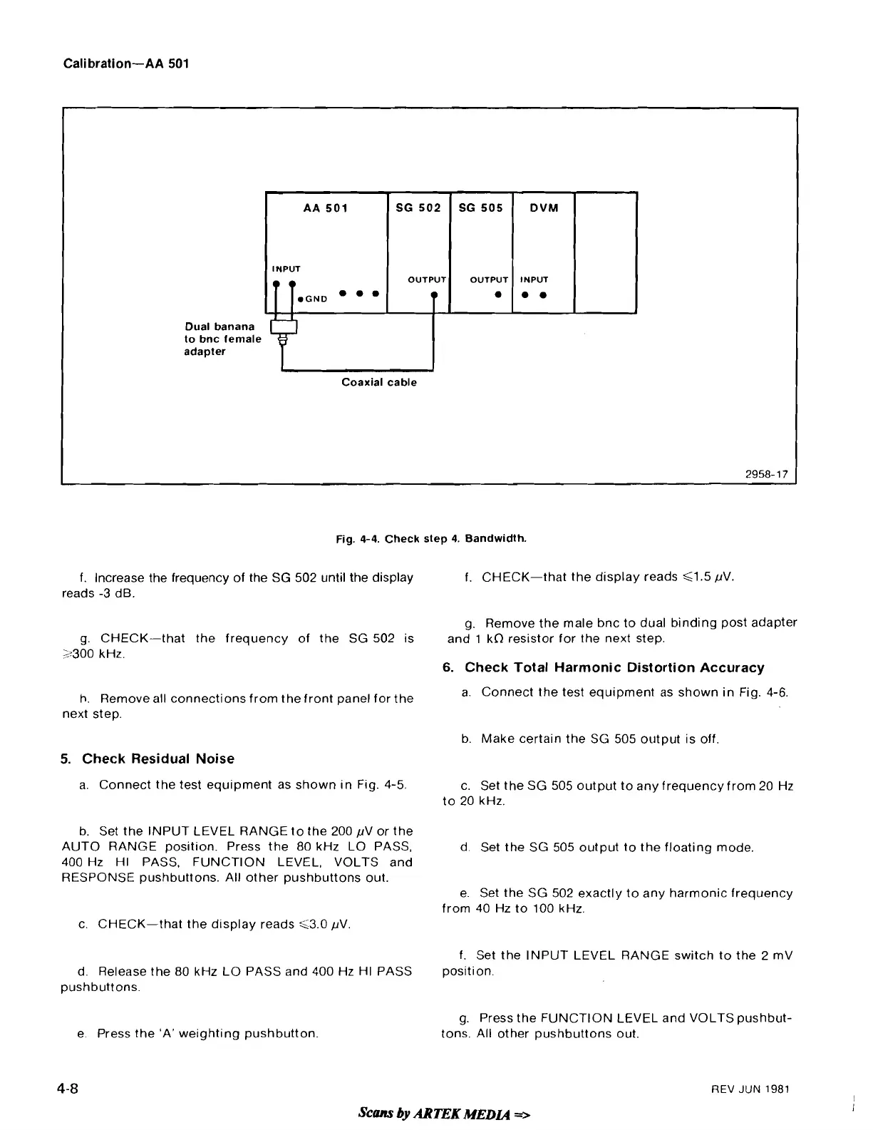
Fig.
4-4.
Check step
4.
Bandwidth.
f. Increase the frequency of the
SG
502 until the display
reads
-3
dB.
g. CHECK-that the frequency of the SG 502 is
2300 kHz.
h.
Remove all connections from the front panel for the
next step.
5.
Check Residual Noise
a. Connect the test equipment as shown in Fig. 4-5.
b. Set the INPUT LEVEL RANGE to the 200 pV or the
AUTO RANGE position. Press the 80 kHz LO PASS,
400 Hz HI PASS, FUNCTION LEVEL, VOLTS and
RESPONSE pushbuttons. All other pushbuttons out.
f. CHECK-that the display reads
G1.5 pV.
g. Remove the male bnc to dual binding post adapter
and
1
kfl resistor for the next step.
6.
Check Total Harmonic Distortion Accuracy
a. Connect the test equipment as shown in Fig. 4-6.
b. Make certain the SG 505 output is off
c. Set the SG 505 output to any frequency from 20 Hz
to 20 kHz.
d. Set the SG 505 output to the floating mode.
e. Set the SG 502 exactly to any harmonic frequency
from 40 Hz to 100 kHz.
c. CHECK-that the display reads G3.0 pV
d. Release the 80 kHz LO PASS and 400 Hz HI PASS
pushbuttons.
e. Press the 'A' weighting pushbutton.
f. Set the INPUT LEVEL RANGE switch to the 2
mV
position.
g. Press the FUNCTION LEVEL and VOLTS
pushbut-
tons. All other pushbuttons out.
4-8
REV
JUN
1981
Scans
by
ARTEK
MEN
=>
 Loading...


