1.
Check lnput Impedance
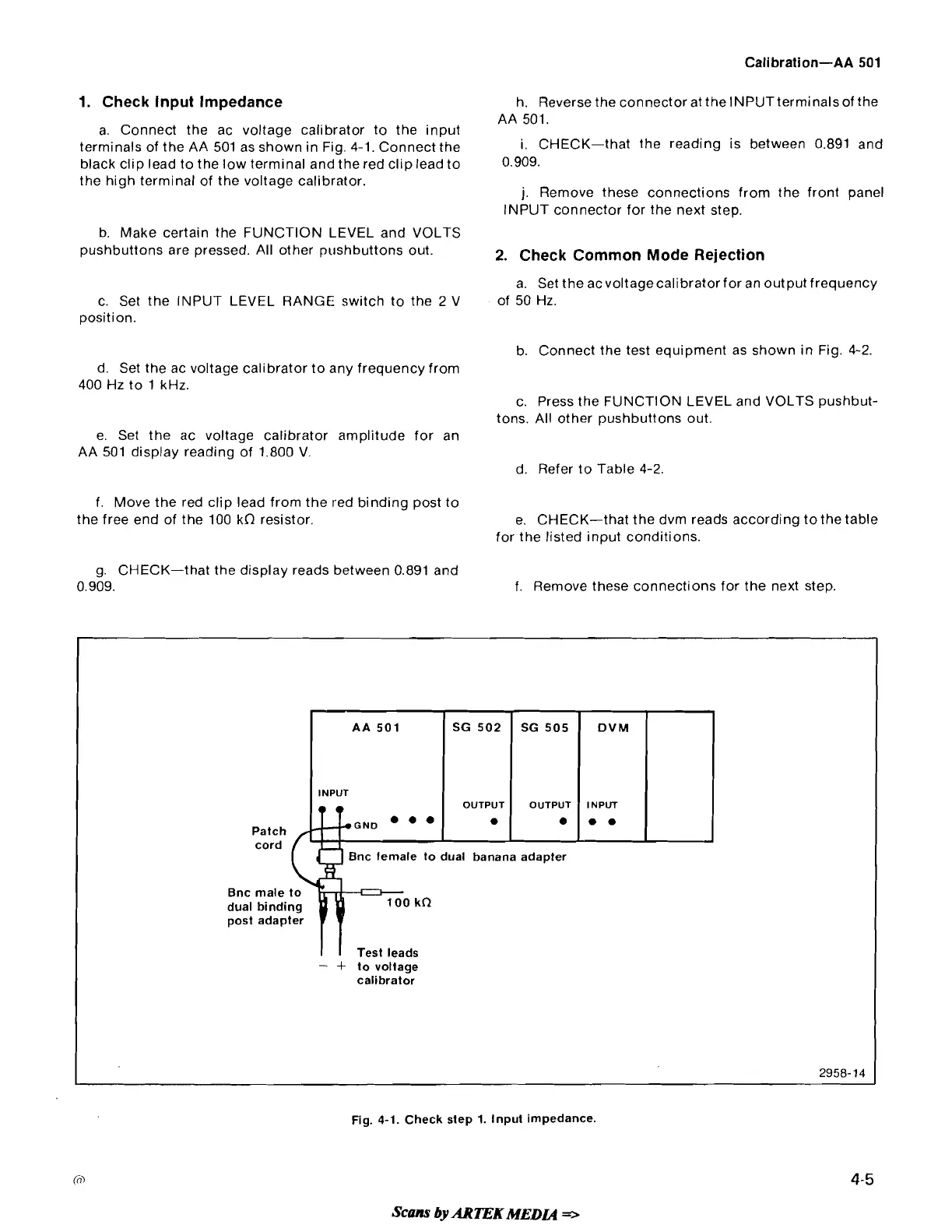
a. Connect the ac voltage calibrator to the input
terminals of the AA 501 as shown in Fig.
4-1. Connect the
black clip lead to the low terminal and the red clip lead to
the high terminal of the voltage calibrator.
b. Make certain the FUNCTION LEVEL and VOLTS
pushbuttons are pressed. All other
pushbuttons out.
c. Set the INPUT LEVEL RANGE switch to the
2
V
position.
h. Reverse the connector at the INPUT terminals of the
AA 501.
i. CHECK-that the reading is between 0.891 and
0.909.
j.
Remove these connections from the front panel
INPUT connector for the next step.
2.
Check Common Mode Rejection
a. Set the acvoltagecalibrator for an output frequency
of 50 Hz.
b. Connect the test equipment as shown in Fig.
4-2.
d. Set the ac voltage calibrator to any frequency from
400 Hz to 1 kHz.
c. Press the FUNCTION LEVEL and VOLTS
pushbut-
tons. All other pushbuttons out.
e. Set the ac voltage calibrator amplitude for an
AA 501 display reading of 1.800 V.
d. Refer to Table
4-2.
f. Move the red clip lead from the red binding post to
the free end of the 100
kn resistor.
g. CHECK-that the display reads between 0.891 and
0.909.
e. CHECK-that the dvm reads according tothetable
for the listed input conditions.
f. Remove these connections for the next step.
-
Patch
cord
Bnc female to dual banana adapter
Bnc male
dual bindi
post adap
-
f
to voltage
calibrator
2958-14
Fig.
4-1.
Check step
1.
Input impedance.
Scans
by
ARTEKMEDCQ
=r
 Loading...


