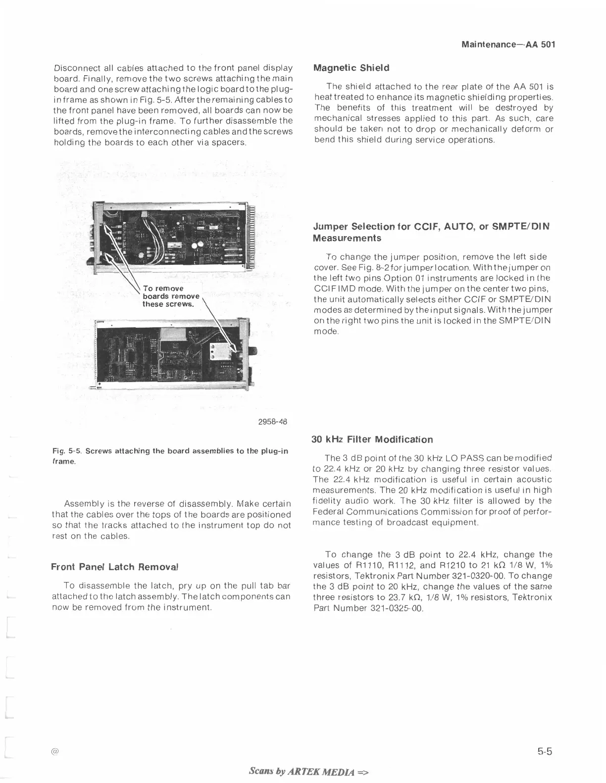
Disconnect all cables attached to the front panel display
board. Finally, remove the two screws attaching the main
board and one screw attaching the logic board tothe plug-
in frame as shown in Fig. 5-5. Afterthe remaining cablesto
the front panel have been removed, all boards can now be
lifted from the plug-in frame. To further disassemble the
boards, remove the interconnecti ng cables and the screws
holding the boards to each other via spacers.
,
\
To remove
boards remove
these screws.
\
Magnetic Shield
The shield attached to the rear plate of the AA 501 is
heat treated to enhance its magnetic shielding properties.
The benefits of this treatment will be destroyed by
mechanical stresses applied to this part. As such, care
should be taken not to drop or mechanically deform or
bend this shield during service operations.
Jumper Selection for CCIF, AUTO, or SMPTEIDIN
Measurements
To change the jumper position, remove the left side
cover. See Fig. 8-2forjumperIocation. Withthejumper on
the left two pins option 01 instruments are locked in the
CCI F IMD mode. With the jumper on the center two pins,
the unit automatically selects either CCIF or SMPTWDIN
modes as determined bytheinput siqnals. Withtheiumper
on the right two pins thk unit is locked in the SMPTWDIN
mode.
30
kHz
Filter Modification
Fig.
5-5.
Screws attaching the board assemblies to the
plug-in
frame.
The 3 dB point of the 30 kHz
LO
PASS can be modified
to 22.4 kHz or 20 kHz by changing three resistor values.
The
22.4
kHz modification is useful in certain acoustic
measurements. The 20 kHz modification is useful in high
~~~~~bl~ is the
reverse
of
disassembly, ~~k~ certain
fidelity audio work. The 30 kHz filter is allowed by the
that the cables
over
the
tops
of
the boards
are
positioned
Federal Communications Commission for proof of perfor-
so that the tracks attached to the instrument top do not
mance
testing
Of
equipment.
rest on the cables.
To change the 3 dB point to 22.4 kHz, change the
Front Panel Latch Removal
values of R1110, R1112, and R1210 to 21 kn 1/8
W,
l0/o
resistors, Tektronix Part Number 321-0320-00. To change
To disassemble the latch, pry up on the pull tab bar
the 3 dB point to 20 kHz, change the values of the same
attached to the latch assembly. Thelatch componentscan
three resistors to 23.7 kn, 1/8
W,
1% resistors, Tektronix
now be removed from the instrument.
Part Number 321-0325-00.
Scans
by
AR
TEK
MEDL.4
=>
 Loading...


