Semiconductors
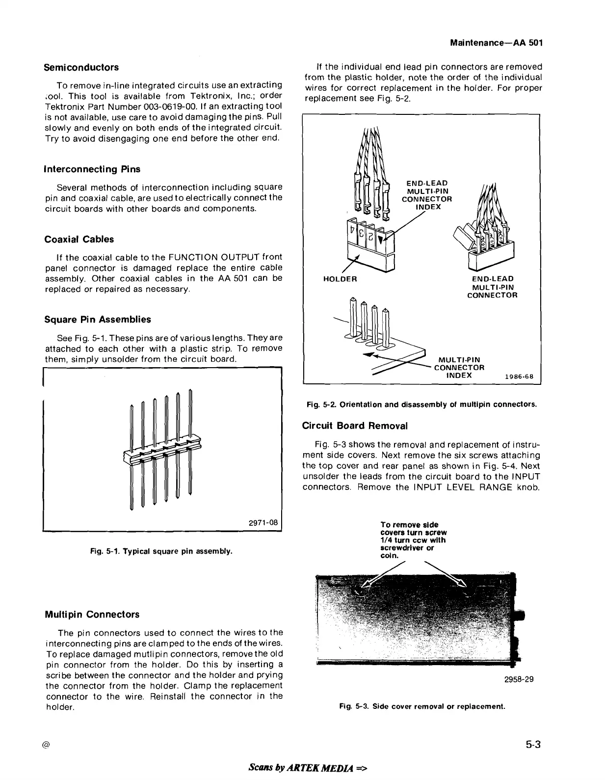
If the individual end lead pin connectors are removed
from the plastic holder, note the order of the individual
To remove in-line integrated circuits use an extracting
,ires
for
correct
replacement in the holder.
F~~
proper
;ool. This tool is available from Tektronix, Inc.; order
replacement
see
~i~,
5-2,
Tektronix Part Number 003-0619-00. If an extracting tool
is not available, use care to avoid damaging the pins. Pull
slowly and evenly on both ends of the integrated circuit.
Try to avoid disengaging one end before the other end.
Interconnecting Pins
Several methods of interconnection including square
pin and coaxial cable, are used to electrically connect the
circuit boards with other boards and components.
Coaxial Cables
If the coaxial cable to the FUNCTION OUTPUT front
panel connector is damaged replace the entire cable
assembly. Other coaxial cables in the AA 501 can be
replaced or repaired as necessary.
Square Pin Assemblies
See Fig.
5-1.
These pins areof variouslengths. They are
attached to each other with a plastic strip. To remove
them, simply unsolder from the circuit board.
END-LEAD
MULTI-PIN
CONNECTOR
END-LEAD
MULTI-PIN
CONNECTOR
MULTI-PIN
CONNECTOR
INDEX
1986-68
Fig. 5-1. Typical square pin assembly.
Multi pin Connectors
The pin connectors used to connect the wires to the
interconnecting pins are clamped to the ends of the wires.
To replace damaged mutlipin connectors, remove the old
pin connector from the holder. Do this by inserting a
scribe between the connector and the holder and prying
the connector from the holder. Clamp the replacement
connector to the wire. Reinstall the connector in the
holder.
Fig. 5-2. Orientation and disassembly of multipin connectors.
Circuit Board Removal
Fig. 5-3 shows the removal and replacement of instru-
ment side covers. Next remove the six screws attaching
the top cover and rear panel as shown in Fig.
5-4.
Next
unsolder the leads from the circuit board to the INPUT
connectors. Remove the INPUT LEVEL RANGE knob.
To remove side
covers turn screw
1/4 turn ccw
wlth
screwdrlver or
coln.
Fig. 5-3. Side cover removal or replacement.
Scans
by
ARTEK
MEDL4
=>
 Loading...


