Operating Instructions-AA
501
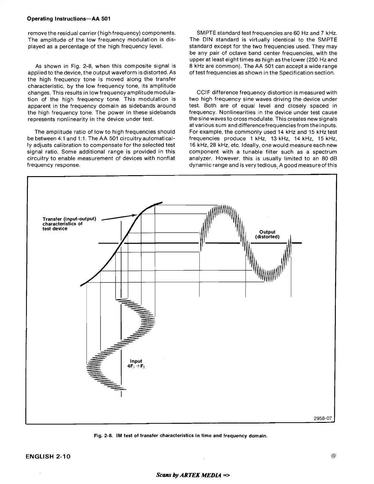
remove the residual carrier (high frequency) components.
The amplitude of the low frequency modulation is dis-
played as a percentage of the high frequency level.
As shown in Fig. 2-8, when this composite signal is
applied to the device, the output waveform isdistorted. As
the high frequency tone is moved along the transfer
characteristic, by the low frequency tone, its amplitude
changes. This results in low frequency
amplitudemodula-
tion of the high frequency tone. This modulation is
apparent in the frequency domain as sidebands around
the high frequency tone. The power in these sidebands
represents nonlinearity in the device under test.
The amplitude ratio of low to high frequencies should
be between
4.1 and 1.1. The AA 501 circuitry automatical-
ly adjusts calibration to compensate for the selected test
signal ratio. Some additional range is provided in this
circuitry to enable measurement of devices with nonflat
frequency response.
SMPTE standard test frequencies are 60 Hz and
7
kHz.
The DIN standard is virtually identical to the SMPTE
standard except for the two frequencies used. They may
be any pair of octave band center frequencies, with the
upper at least eight times as high as
thelower (250 Hzand
8 kHz are common). The AA 501 can accept a wide range
of test frequencies as shown in the Specification section.
CCIF difference frequency distortion is measured with
two high frequency sine waves driving the device under
test. Both are of equal level and closely spaced in
frequency. Nonlinearities in the device under test cause
the sine wavesto cross modulate. This creates new signals
at various sum
anddifferencefrequenciesfrom
theinputs.
For example, the commonly used 14 kHz and 15
kHztest
frequencies produce 1 kHz, 13 kHz, 14 kHz, 15 kHz,
16 kHz, 28 kHz, etc. Ideally, one would measureeach new
component with a tunable filter such as a spectrum
analyzer. However, this is usually limited to an 80 dB
dynamic range and is very tedious, Agood measureof this
Fig.
2-8.
IM
test of transfer characteristics in time and frequency domain.
Transfer (input-output)
characteristics of
test device
I
2958-07
ENGLISH
2-10
-
Scam
by
ARTEK
MEDLd
=>
 Loading...


