Performance Tests
CSA7404B, TDS7704B, TDS7404B, TDS7254B & TDS7154B Service Manual
4-85
NOTE. To eliminate errors caused by the cables and adapters, the measurements
are repeated and averaged after swapping the channel position of the cables.
i. Repeat the procedure from step 2.a through 2.e.
j. Again use the cursors to measure the skew from CH 1 to CH 2, CH 1 to
CH 3, and C H 1 to CH 4. Write down these numbers in the second
measurement column of Table 4--8. Note that these numbers may be
either positive or negative.
k. Add the first CH 1 to CH 2 skew measurement to the second CH 1 to
CH 2 skew measurement and divide the result by 2. Use Table 4--8.
l. Add the first CH 1 to CH 3 skew measurement to the second CH 1 to
CH 3 skew measurement and divide the result by 2. Use Table 4--8.
m. Add the first CH 1 to CH 4 skew measurement to the second CH 1 to
CH 4 skew measurement and divide the result by 2. Use Table 4--8.
n. Check against limits: CHECK that the largest of the three results from
steps k, l, and m is between --30 ps and + 30 ps.
o. Enter the time on the test record.
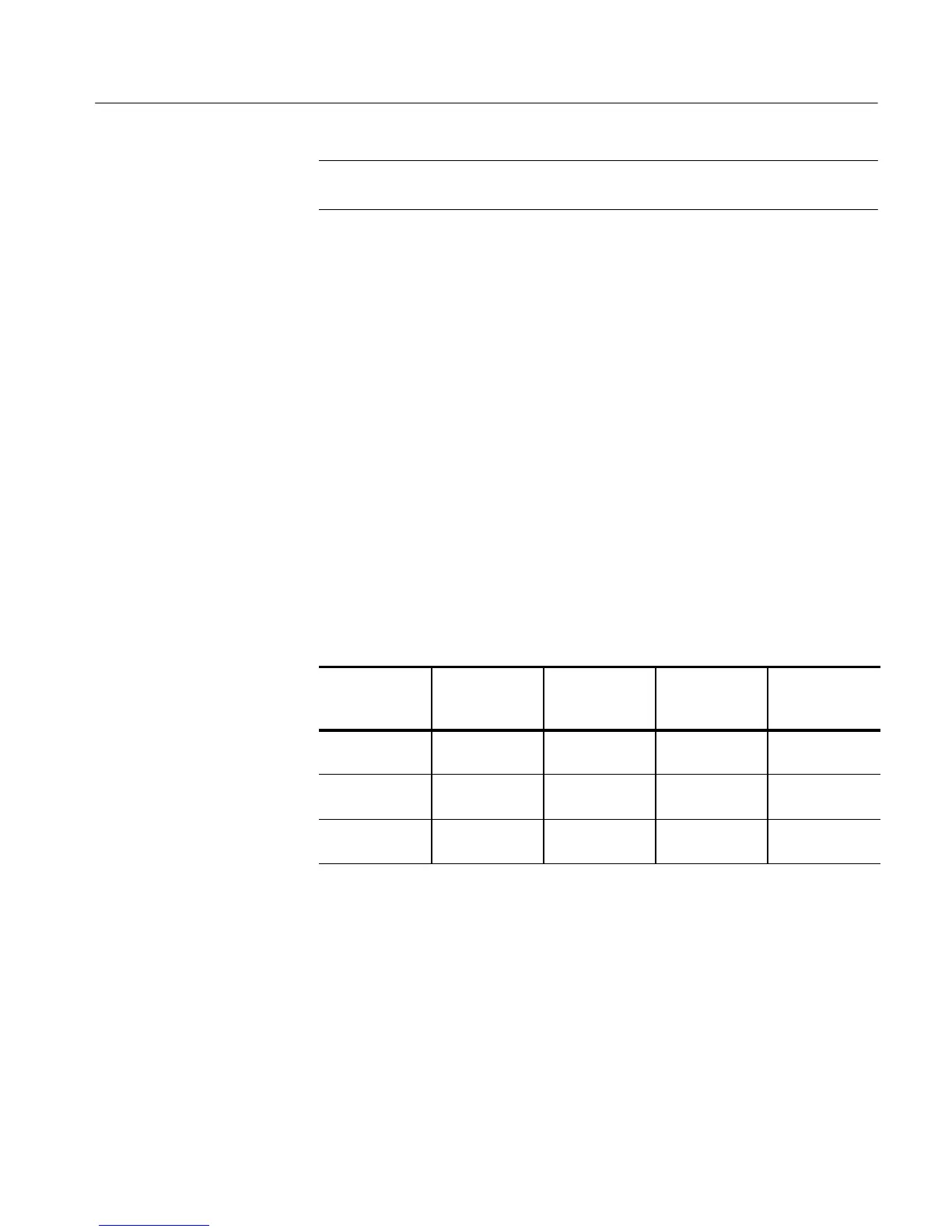
Table 4- 8: Delay between channels worksheet
Coupling
First
measurement
Second
measurement
Add first and
second
measurements
Divide sum
by 2
CH1toCH2
skew
CH1toCH3
skew
CH1toCH4
skew
3. Disconnect the hookup: Disconnect the cable from the generator output at
the input connectors of the channels.

 Loading...


