Brief Procedures
4-14
CSA7404B, TDS7704B, TDS7404B, TDS7254B & TDS7154B Service Manual
H As you rotate the lower multipurpose knob, the square-wave
probe-compensation signal can become triggered and untriggered.
(Leave the signal triggered.)
c. Verify the delayed trigger counter:
H Double click the Trig Delay control to pop up a numeric keypad for
that control.
H Click the keypad to enter a trigger delay time of 1 second and then
click Enter.
H Verify that the trigger READY indicator on the front panel flashes
about once every second as the waveform is updated on-screen.
8. Remove the test hookup: Disconnect the BNC cable from the channel input
and the probe compensation output.
Equipment
required
One BNC cable, such as Tektronix part number 012-0076-00
One TCA-BNC adapt er
One 1.44 Mbyte, 3.5 inch DOS-compatible formatted disk.
Prerequisites None
1. Initialize the instrument:Push the front-panel DEFAULT S ETUP button.
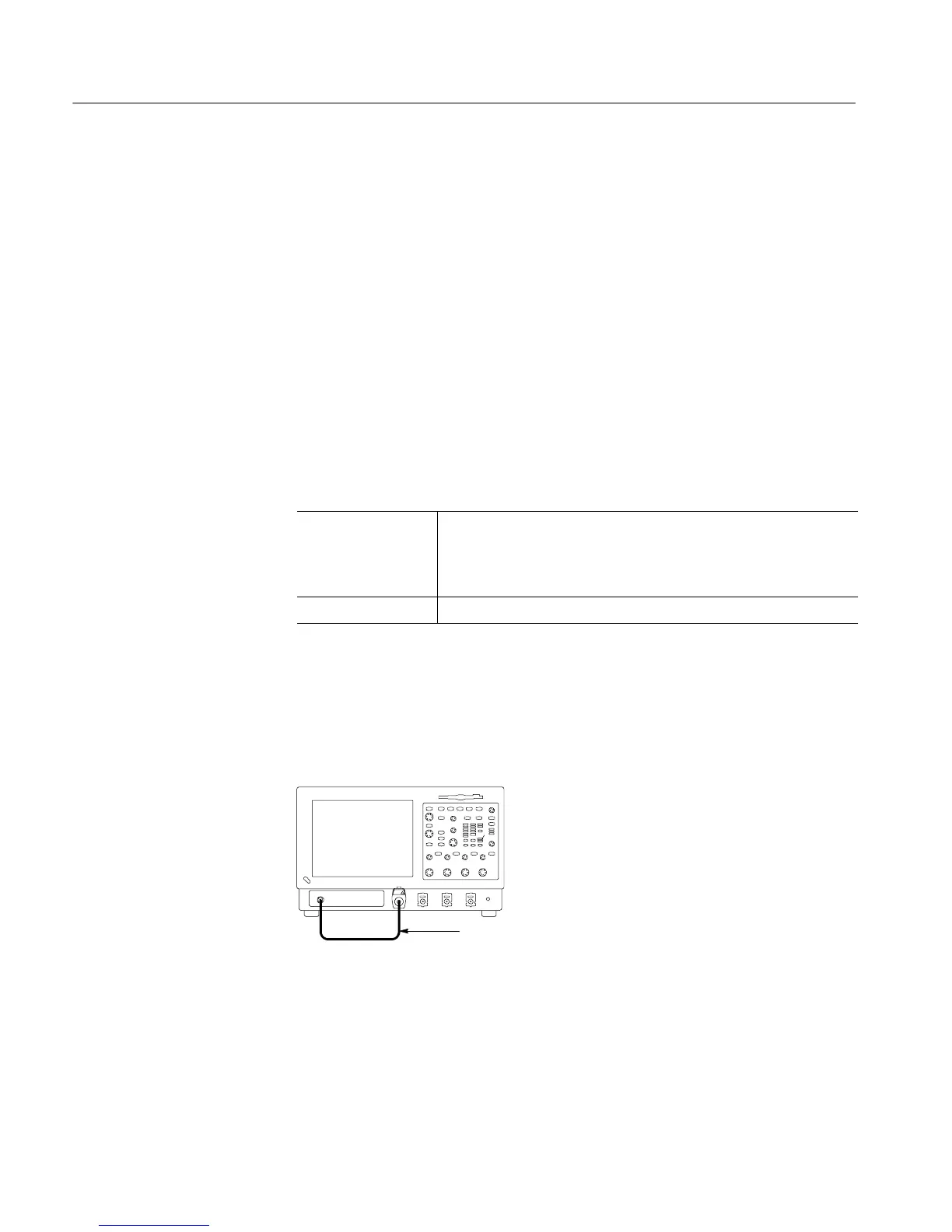
2. Hook up the signal source: Connect the BNC cable from the probe com-
pensation output to the CH 1 input through a TCA-BNC adapter as shown in
Figure 4--6.
BNC cable from PROBE
COMPENSATION output to
CH 1 input
Instrument under test
Figure 4- 6: Setup for the file system test
3. Insert the test disk: Insert the floppy disk in the floppy disk drive.
4. Set up the instrument: Push the front panel AUTOSET button.
Verify the File System

 Loading...


