Troubleshooting
CSA7404B, TDS7704B, TDS7404B, TDS7254B & TDS7154B Service Manual
6-81
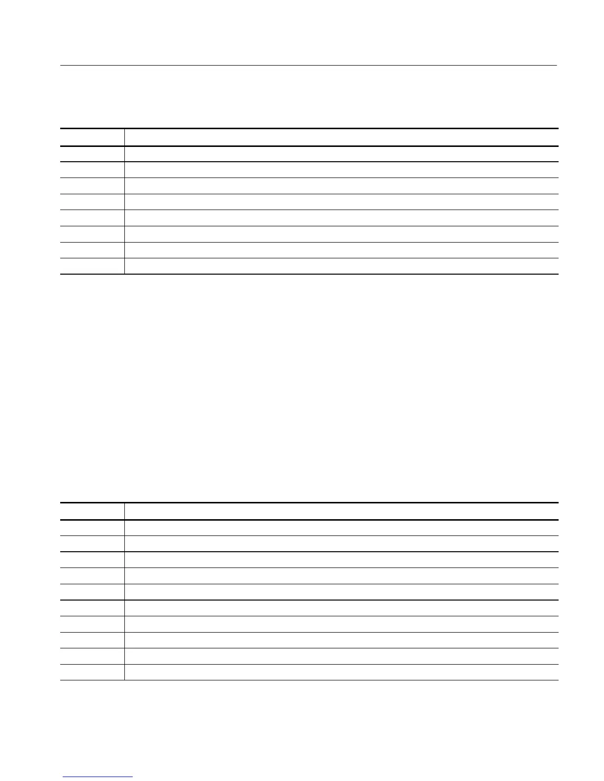
Table 6- 10: Different bus routines upper-nibble high-byte f unctions
Value Description
0 Function 0, disable all devices on the bus.
1 Function 1, static devices initialization on the bus.
2 Function 2, output device initi alization on the bus.
3 Function 3, input device initi alization on the bus.
4 Function 4, IPL device initialization on the bus.
5 Function 5, general device initiali z ation on the bus.
6 Function 6, error reporting for the bus.
7 Function 7, add-on ROM initialization for all buses.
BIOS Beep Codes
When the MicroATX board powers-on a number of the BIOS checkpoints
generate an audible ’beep’ code on failure using the standard PC speaker (also
routed through the board audio system). The beep codes are listed in Table 6--11.
Codes are also written to I/O port 80h and the video adapters. External ROM
modules may issue a series of tones on error detection.
The BIOS generates one short beep if the power up self tests complete with out
error.
If your instrument does not contain a speaker, attach a speaker to the display-
adapter board square pins to hear the codes.
Table 6- 11: Beep codes
Beep code Error message
1 Refresh failure
2 Cannot reset parity
3 Memory failure, first 64 KB
4 Timer failure
5 Not used
6 Cannot toggle 8042 GateA20
7 Exception interrupt error
8 Display memory R/W error
9 Not used
10 CMOS Shutdown register test error

 Loading...


