Performance Tests
CSA7404B, TDS7704B, TDS7404B, TDS7254B & TDS7154B Service Manual
4-99
Trigger System Checks
These procedures check those characteristics that relate to the trigger system and
are listed as checked in Specifications.
Equipment
required
One sine wave generator (Item 12)
One 2X attenuator (Item 26)
One 50 Ω, precision coaxial cable (Item 4)
One SMA male-to-female BNC adapter (Item 19)
Prerequisites See page 4--17
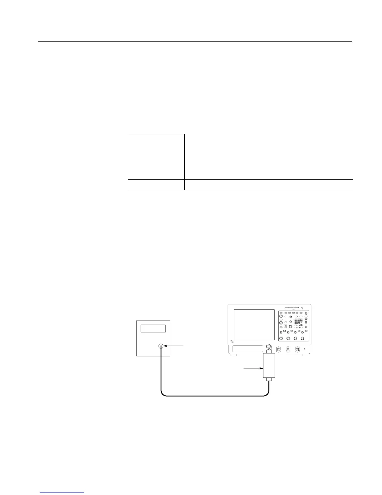
1. Install the test hookup and preset the instrument controls:
a. Initialize the instrument: Press the DEFAULT SETUP button.
b. Modify the default setup: Set the horizontal SCALE to 2.5 ns.
c. Hook up the test-signal source: Connect the output of the sine wave
generator (Item 12) to CH 1.
Do this through a 50 Ω precision coaxial cable, followed by a 2X
attenuator and adapter. See Figure 4--25.
Instrument under test
50 Ω Coaxial cable
Sine wave generator
Output
2X Attenuator
Figure 4- 25: Initial test hookup
d. Set the trigger mode: Press the Trigger MODE button to toggle it to
NORMAL.
Check Time Accuracy for
Pulse, Glitch, Timeout,
and Width Triggering

 Loading...


