Specification-PS
50
1
0
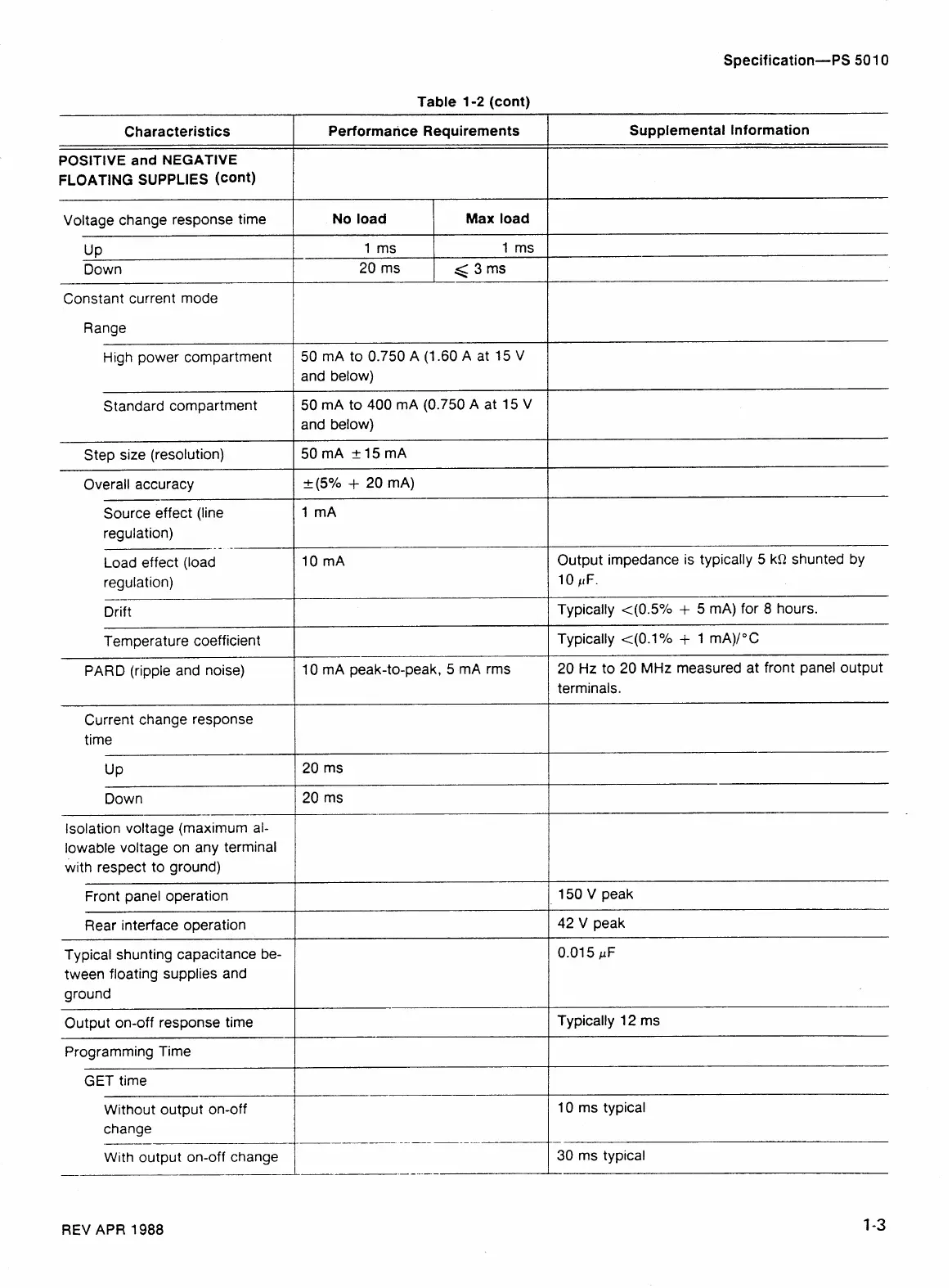
Table
1-2
(cont)
Characteristics
POSITIVE
and
NEGATIVE
FLOATING SUPPLIES
(cant)
Voltage change response time
UP
Down
Constant current mode
Range
High power compartment
Standard compartment
Step size (resolution)
Overall accuracy
Source effect (line
regulation)
--
--
Load effect (load
regulation)
Drift
Temperature coefficient
PARD (ripple and noise)
Current change response
time
Down
Isolation voltage (maximum al-
lowable voltage on any terminal
with respect to ground)
Front panel operation
Rear interface operation
Typical shunting capacitance be-
tween floating supplies and
ground
Output on-off response time
Programming Time
GET time
Without output on-off
change
--
With output on-off change
Performarice Requirements Supplemental Information
No load
Max load
1
ms
1
ms
and below)
50
mA to
400
mA
(0.750
A at
15
V
and below)
I
10
mA
Output impedance is typically
5
kR shunted by
10
/tF.
Typically
<(0.S0/0
+
5
mA) for
8
hours.
Typically
<(O.lOh
+
1
mA)I0C
10
mA peak-to-peak,
5
mA rms
20
Hz
to
20
MHz
measured at front panel output
terminals.
I
150
V peak
42
V peak
Typically
12
ms
10
ms typical
REV
APR
1988
 Loading...


