Table
1-2
(cont)
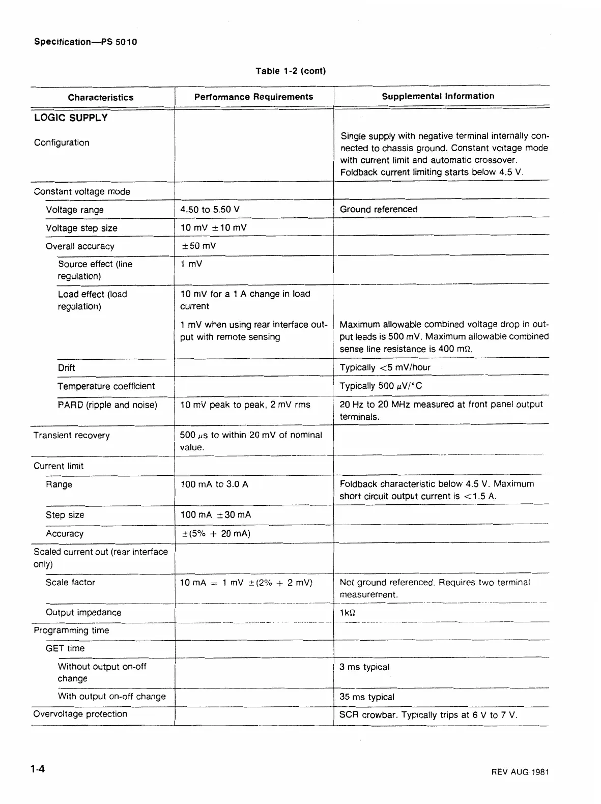
LOGIC
SUPPLY
Characteristics
Performance Requirements
Configuration
Constant voltage mode
Voltage range
Voltage step size
Overall accuracy
Source effect (line
regulation)
Load effect (load
regulation)
Supplemental Information
Drift
4.50
to
5.50
V
10
mV
+I0
mV
+50
mV
1
mV
10
mV for
a
1
A change in load
Temperature coefficient
Single supply with negative terminal internally
con-
nected to chassis ground. Constant voltage mode
with current limit and automatic crossover.
Foldback current limiting starts below
4.5
V.
Ground referenced
1
mV when using rear interface out-
put with remote sensing
Typically
500
pVI0 C
Transient recovery
current
I
Maximum allowable combined voltage drop in out-
put leads is
500
mV. Maximum allowable combined
sense line resistance is
400
mQ.
Typically
t
5
mV/hour
PARD
(r
Current limit
Range
Step size
Accuracy
Scaled current out (rear interface
500
ps to within
20
mV of nominal
value.
----
--
only)
Scale factor
GET time
Without output on-off
3
ms typical
I
terminals.
---
--
100
mA to
3.0
A
100
mA
230
mA
+(5%
+
20
mA)
Output impedance
Programming time
Foldback characteristic below
4.5
V. Maximum
short circuit output current is
<
1.5
A.
----
10
mA
=
1
mV
1(2%
+
2
mV)
REV
AUG
1981
Not ground referenced. Requires two terminal
.--.
_
.
.. _.
..._.
-
change
With output on-off change
Overvoltage protection
1
kl'l
-__-
35
ms typical
SCR
crowbar. Typically trips at
6
V to
7
V.
 Loading...


