e-STUDIO162/162D/151/151D ELECTRICAL SECTION 13 - 2
2. Circuit descriptions
A. Main PWB (MCU)
(1) General
The MCU PWB is composed of:
• CPU peripheral section which performs mechanical sequence
control, U/I, and each function job management.
The CPU connects with the ASIC and memory by use of the system
bus and performs jog management and sequence control of the
whole engine.
• Image process ASIC which performs image process, CCD control,
LSU control, and print control.
• OA982 peripheral section which performs E-Sort and FAX control.
The OA982 performs image data input/output with the ASIC,
SDRAM memory management, and communication with USB2.0
devices.
• I/F section for USB2.0 and IEEE1284 control. (For the AL series,
IEEE1284 is not available.)
• Motor control circuit
• Mechanical load, sensor I/O circuit
It performs control and management of the process, the transport
loads, the fusing, the optical, and the operation panel sections for exe-
cuting a series of copy/print/scan operations.
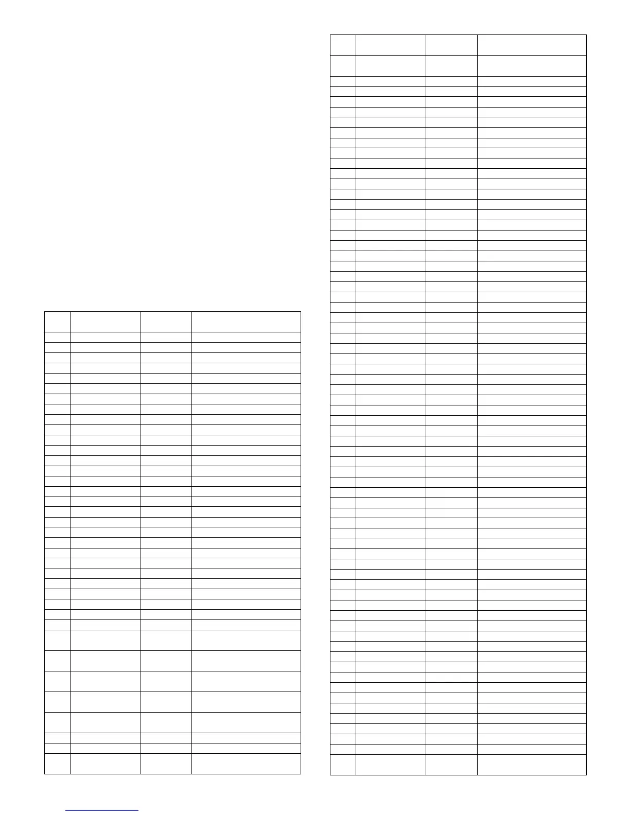
(2) CPU signal table (H8S/2321)
PIN
No.
Signal code
Input/
Output
Operating
1 /CS1 Output SRAM chip select
2 /CS0 Output Flash ROM chip select
3 GND DGND
4 GND DGND
5Vcc CPU3.3V
6 A0 Output Address bus
7 A1 Output Address bus
8 A2 Output Address bus
9 A3 Output Address bus
10 GND DGND
11 A4 Output Address bus
12 A5 Output Address bus
13 A6 Output Address bus
14 A7 Output Address bus
15 A8 Output Address bus
16 A9 Output Address bus
17 A10 Output Address bus
18 A11 Output Address bus
19 GND DGND
20 A12 Output Address bus
21 A13 Output Address bus
22 A14 Output Address bus
23 A15 Output Address bus
24 A16 Output Address bus
25 A17 Output Address bus
26 A18 Output Address bus
27 A19 Output Address bus
28 GND DGND
29 A20 Pull-Up
30 PSW Interruption
level input
Print SW
31 SPPD Interruption
level input
ADF paper sensor
32 CCD_TG Interruption
level input
CCD horizontal sync signal
33 MHPS Interruption
level input
Mirror Home Position
34 /CPUSYNC Interruption
level input
Horizontal sync (ASIC)
35 GND DGND
36 GND DGND
37 FW Interruption
level input
Zero cross signal
38 ARB_INT Interruption
level input
ASIC interruption
39 Vcc CPU3.3V
40 D0 Data I/O Data bus
41 D1 Data I/O Data bus
42 D2 Data I/O Data bus
43 D3 Data I/O Data bus
44 GND DGND
45 D4 Data I/O Data bus
46 D5 Data I/O Data bus
47 D6 Data I/O Data bus
48 D7 Data I/O Data bus
49 D8 Data I/O Data bus
50 D9 Data I/O Data bus
51 D10 Data I/O Data bus
52 D11 Data I/O Data bus
53 GND DGND
54 D12 Data I/O Data bus
55 D13 Data I/O Data bus
56 D14 Data I/O Data bus
57 D15 Data I/O Data bus
58 Vcc CPU3.3V
59 POFF Output Shut off control
60 TxD1 Output For debug
61 SDA Output EEPROM Data bus
62 SCL Output EEPROM clock
63 LCDRS Output LCD control
64 LCDE Output LCD control
65 GND DGND
66 CS4 (FAX) Chip select (FAX)
67 GND DGND
68 GND DGND
69 RY/BY Input Flash Busy signal
70 LCDDB4 Output LCD control
71 LCDDB5 Output LCD control
72 BZR Output Buzzer signal
73 LCDDB7 Output LCD control
74 LCDDB6 Output LCD control
75 Reset OUT1 Output Reset signal
76 DMT0 Output Duplex Motor signal
77 DMT1 Output Duplex Motor signal
78 DMT2 Output Duplex Motor signal
79 DMT3 Output Duplex Motor signal
80 WDTOVF Output NC Pull-Up
81 /RES Input Reset
82 NMI Output NC Pull-Up
83 STBY Output NC Pull-Up
84 Vcc CPU3.3V
85 XTAL Input Clock
86 EXTAL Output Clock
87 GND DGND
88 CPUCLK Output NC
89 Vcc CPU3.3V
90 PRINTST Output Print start signal
91 /RD Output Read signal
92 /HWR Output Write signal (High address)
93 /LWR Output Write signal (Low address)
94 SELIN3 Output HC151 select signal
95 SELIN2 Output HC151 select signal
96 SELIN1 Output HC151 select signal
97 ESSTS Output E-sort control
98 ESCMD Input E-sort control
99 GND DGND
100 GND DGND
101 ESSRDY Input E-sort control
102 ESCRDY Output E-sort control
103 AVcc CPU3.3V
104 Vref CPU3.3V
105 RTH Analog
input
Fusing thermistor
PIN
No.
Signal code
Input/
Output
Operating
e-STUDIO162_151.book 2 ページ 2004年12月2日 木曜日 午後9時37分
 Loading...