Unit Weight and Rigging
OAU-SVX007A-EN 67
Before proceeding, refer to tables in Unit Weight section for
typical unit operating weights and Figure 104, p. 66 for rigging
drawing.
1. Remove the shipping crate from around the unit.
2. Rig the unit as shown in Figure 104, p. 66. Attach
adequate strength lifting slings to all four lifting brackets in
the unit base rail. Do not use cables, chains, or slings
except as shown.
3. Install a lifting bar, as shown in Figure 104, p. 66, to protect
the unit and to facilitate a uniform lift. The minimum
distance between the lifting hook and the top of the unit
should be 7 feet.
4. Test-lift the unit to ensure it is properly rigged and
balanced, make any necessary rigging adjustments.
5. Lift the unit and position it into place. Remove fork pockets
prior to setting on the curb.
6. Downflow units; align the base rail of the unit with the curb
rail while lowering the unit onto the curb. Make sure that the
gasket on the curb is not damaged while positioning the
unit.
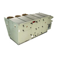
Rigging
Figure 104. Rigging and center-of-gravity data
SPREADER BARS
LENGTH
WIDTH
DETAIL A
SCALE 1 : 12
LIFTING POINTS
(8 LOCATIONS)
8-point lift,
horizontal
return with
energy wheel
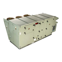
Figure 105. Rigging and center-of-gravity data
/(1*7+
:,'7+
635($'(5
%$56
6&5(:3,16+$&./(
/2&$7,216
4-point lift
Model: OAB
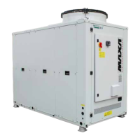
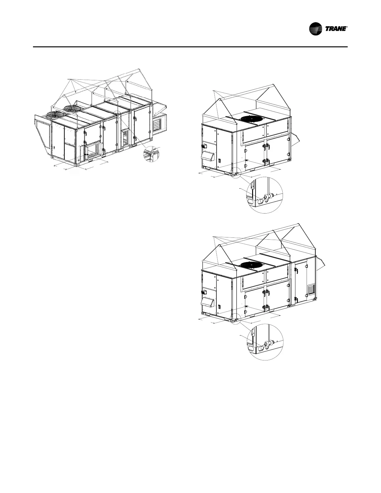
/(1*7+
:,'7+
635($'(5
%$56
6&5(:3,16+$&./(
/2&$7,216
6-point lift
Model: OAB
 Loading...