Installation
OAU-SVX007A-EN 75
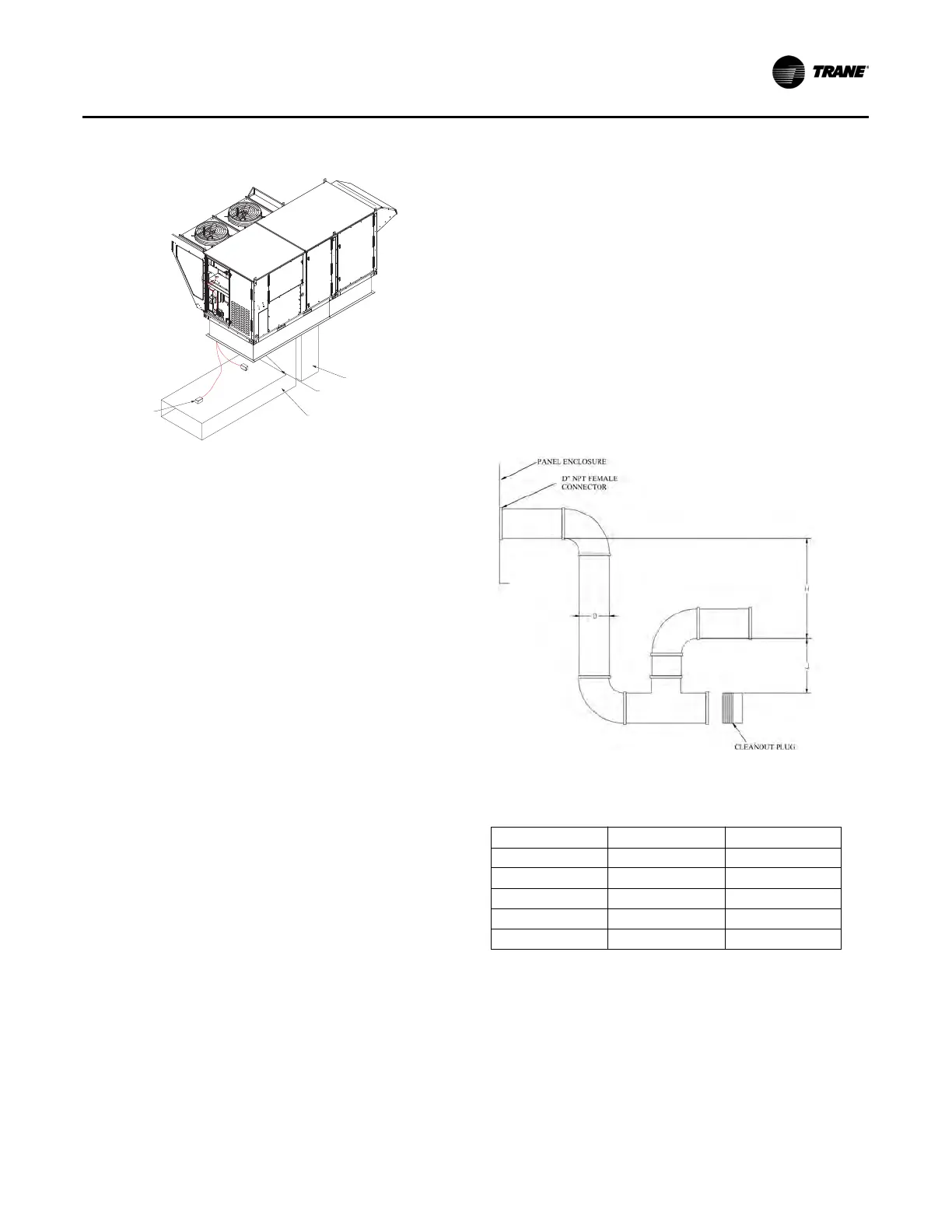
• Discharge Air sensor should be placed in the center of the
ductwork at least 4 feet from the unit or after the first 90°
bend.
General Unit Requirements
The checklist listed below is a summary of the steps required
to successfully install a commercial unit. This checklist is
intended to acquaint the installing personnel with what is
required in the installation process. It does not replace the
detailed instructions called out in the applicable sections
of this manual.
Condensate Drain Configuration
OAU units are selected based on dehumidification capability.
As such, condensate can form at a high rate. Therefore, the
OAU drain pan and condensate line are sized and designed
accordingly. However, an often-overlooked element of proper
condensate drainage is proper P-Trap and drain line sizing and
installation. An incorrectly-designed and -installed P-Trap can
restrict condensate flow or cause water in the condensate
drain pan to “spit” or “geyser,” which may cause condensate
overflow. Carefully install and trap the drain pan to ensure
adequate condensate removal under all conditions.
An evaporator condensate drain connection is provided on
each unit.
A condensate trap must be installed at the unit due to the drain
connection located on the “negative pressure” side of the fan.
Install the P-Trap using the guidelines in Figure 116, p. 75.
Pitch drain lines connected to P-Trap at least 1/2 inch for every
10 feet of horizontal run to ensure proper condensate flow. Do
not allow the horizontal run to sag, causing a possible double-
trap condition which could result in condensate backup due to
“air lock”.
Notes:
1. Pitch drain at least 1/2 in. per 10 ft horizontal run.
2. Condensate drain pan will not drain properly if P-trap is not primed and of
adequate height to allow for cabinet operating negative pressure.
3. Pressure is the static pressure measured in the drain pan. If unsure of
operating static, use the design total static.
4.For variable air volume applications, pressure must be at the maximum
operating static.
Figure 115. Extreme transition in duct work
Check the unit for shipping damage and material
shortage. File a freight claim and notify appropriate sales
representative if damage or shortage is discovered.
Verify that the unit nameplate model, options, and voltage
are correct.
Verify that the installation location of the unit will provide
the required clearance for proper operation.
Assemble and install the roof curb (if applicable). Refer to
the latest edition of the curb installers guide that ships with
each curb kit. Check curb for level installation; if not level,
shim as required.
Rigging unit (refer to “Unit Weight and Rigging,” p. 62).
Set the unit onto the curb; check for level.
Ensure unit-to-curb seal is tight and without buckles or
cracks.
Install and connect proper condensate drain line to the
evaporator condensate pan drain connection (see
Figure 116, p. 75).
RETURN DUCT
SUPPLY DUCT
EXTREME TRANSITION IN DUCTWORK
CAN CAUSE RESTRICTION.
DISCHARGE AIR SENSOR
LOCATION
Figure 116. Condensate trap installation
Table 8. Condensate P-Trap sizing based on static
pressure
Pressure (In. WC) H J
1 2 1
2 3 1.5
3 4 2
4 5 2.5
5 6 3
 Loading...