Installation
84 OAU-SVX007A-EN
All vent pipe joints must be sealed to prevent leakage. Follow
the instructions provided with the approved venting materials.
Vent pipe shall be sized as follows:
The total equivalent length of vent pipe must not exceed 50 ft
(15.25 m). Equivalent length is the total length of straight
sections, plus 5 ft (1.52 m) for each 90° elbow and 2.5 ft
(0.76 m) for each 45° elbow.
The vent system must also be installed to prevent collection of
condensate. Pitch horizontal pipe runs downward 1/4 in./ft
(21 mm/m) toward the outlet to permit condensate drainage.
Insulate vent pipe exposed to cold air or routed through
unheated areas. Insulate vent pipe runs longer than 10 ft
(3 m). Insulation should be a minimum of 1/2 in. (12 mm) thick
foil faced fiberglass of 1-1/2# density. Maintain 6 in. (152 mm)
clearance between vent pipe and combustible materials.
An approved Breidert Type L, Field Starkap or equivalent vent
cap must be provided. Vent cap inlet diameter must be the
same as the vent pipe diameter. The vent terminal must be at
least 12 in. (305 mm) from the exterior wall that it passes
through to prevent degradation of building material by flue
gases. The vent terminal must be located at least 12 in.
(305 mm) above grade, or in snow areas, at least 3 ft (1 m)
above snow line to prevent blockage. Additionally, the vent
terminal must be installed with a minimum horizontal clearance
of 4 ft (1.2 m) from electric meters, gas meters, regulators or
relief equipment.
Through-the-wall vents shall not terminate over public
walkways or over an area where condensate or vapor could
create a nuisance or hazard. Provide vent termination
clearances to building or structure features as follows:
Hot Water Connection Size and Location
Input ratings Diameter pipe to use
Btu/h W in. mm
75000–149999 21980–43958 5 126
150000–400000 43960–117228 6 152
Structure Minimum Clearance
Door, window or gravity inlet 4 ft (1.2 m) below
4 ft (1.2 m) horizontally
1 ft (305 mm) above
Forced air inlet within 10 ft (3 m) 3 ft (0.91 m) above
Adjoining building or parapet 6 ft (1.8 m)
Adjacent public walkways 7 ft (2.1 m) above grade
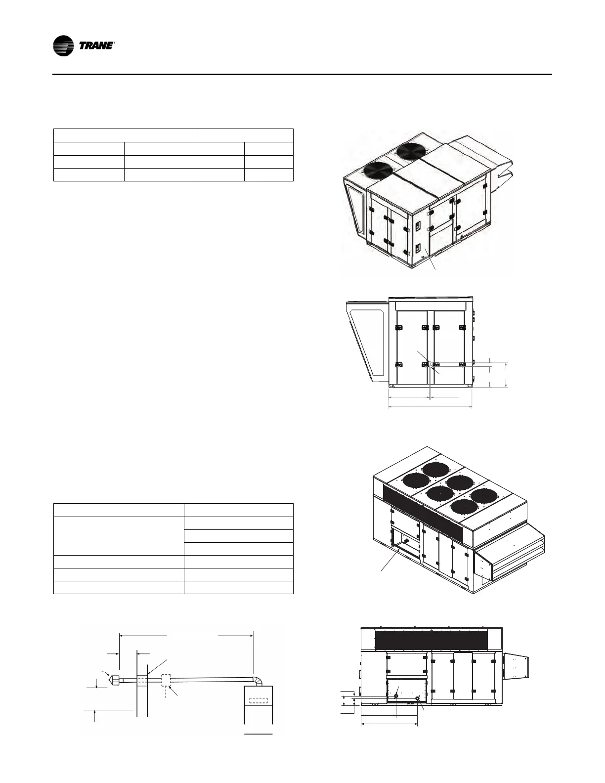
Figure 139. Horizontal venting—category III
5 ft (1.52 m) Min.
50 ft (15.25 m) Max.
Equivalent Length
1 ft (305 mm) Min.
2 in (51 mm) Clearance
Thimble with
2 in. (51 mm) Fiberglass Insulation
Approved
Vent Terminal
3 ft (0.91 m) Min.
Above Highest Snowfall
Condensate Drain
With Trap, If Required
By Local Codes
Heating Appliance
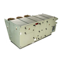
Figure 140. OAD water inlet and outlet, in. (cm)
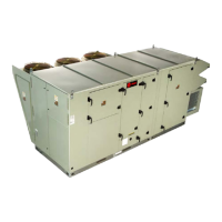
Figure 141. OAN water inlet and outlet, in. (cm)
Water
inlet
Water
outlet
2.865 (7.3)
15.943
(40.5)
18.807
(47.8)
31.055 (78.9) 0.890 (2.3)
63.000 (160.0)
Installing contractor to
cut holes in cabinet side wall
for water pipe penetration
(2 in. [5.1 cm] nominal MNPT).
INSTALLING CONTRACTOR TO CUT HOLES
IN CABINET SIDE PANEL FOR WATER PIPE
PENETRATION (3" NOMINAL MNPT)
WATER INLET
WATER OUTLET
27.500 45.096
9.556
12.902
72.596
3.347
 Loading...