Installation
OAU-SVX007A-EN 89
DC Conductors
Factory-Provided Sensors
A discharge temperature sensor (VELSEN-0021) will be
factory-provided for field installation in the supply duct. Refer
to Figure 149, p. 108 for installation instructions.
If space control is selected, a combination space temperature/
humidity sensor (BAYSENS036A) will be factory-provided for
field installation in the space. Refer to Figure 150, p. 109 for
installation instructions.
If multi-zone VAV control is selected, a static pressure sensor
(VELCON-0976) will be factory-provided for field installation in
the supply duct or space. Refer to Figure 152, p. 111 for
installation instructions.
If modulating OA/RA dampers w/economizer and an exhaust
fan are selected, a duct static pressure sensor
(VELCON-0350) will be factory-provided for field installation in
the return duct. Refer to Figure 152, p. 111 for installation
instructions.
Table 13. Zone sensor module wiring
Distance from Unit to Control Recommended Wire Size
000–150 feet
0–45.7 m
22 gauge
0.33 mm
2
151–240 feet
46–73.1 m
20 gauge
0.50 mm
2
241–385 feet
73.5–117.3 m
18 gauge
0.75 mm
2
386–610 feet
117.7–185.9 m
16 gauge
1.3 mm
2
611–970 feet
186.2–295.7 m
14 gauge
2.0 mm
2
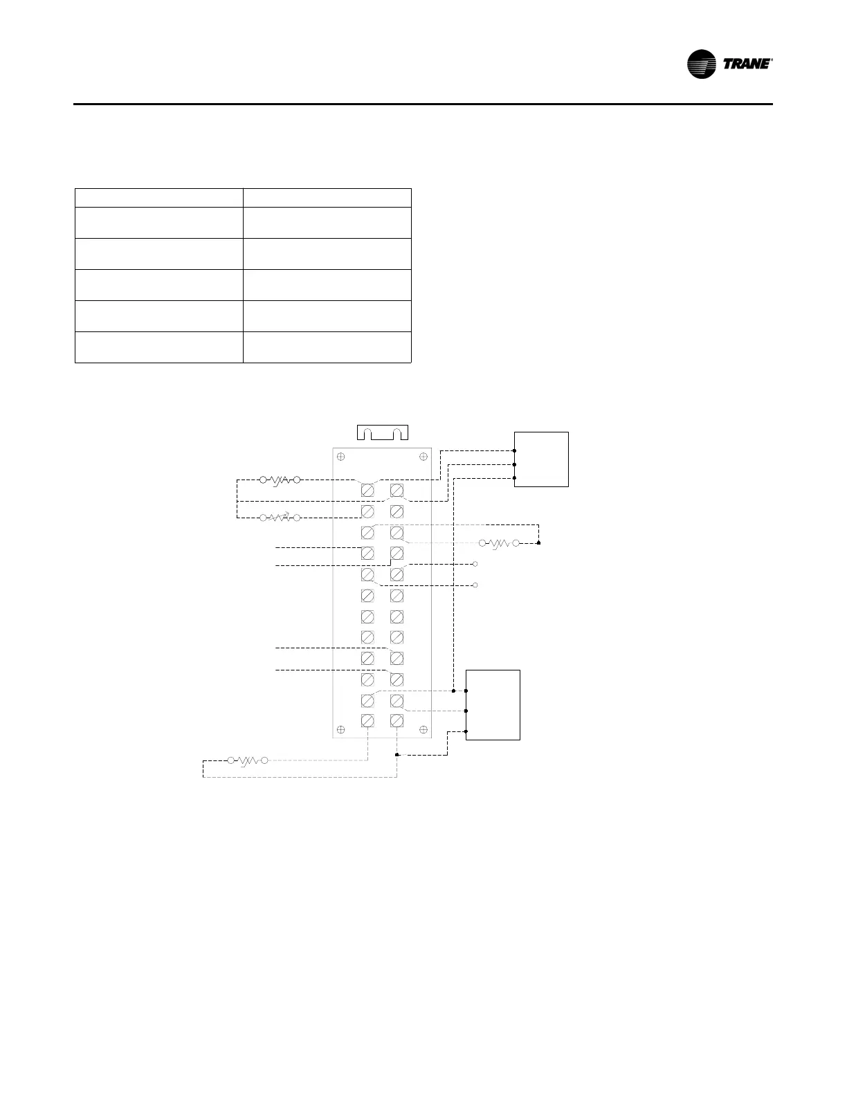
Figure 142. OAUTS connection B
OAUTS
12
34
56
7
8
910
11 12
13
14
15 16
17 18
19 20
21 22
23
24
REMOVE JUMPER AND INSTALL FIELD
SUPPLIED DRY CONTACT OR SWITCH.
CLOSURE BETWEEN OAUTS-7 AND OAUTS-8
ENABLES "OCCUPIED MODE".
TO SHUT DOWN THE UNIT FOR EMERGENCY STOP,
REMOVE JUMPER FROM OAUTS-9 AND OAUTS-10 AND
INSTALL FIELD SUPPLIED DEVICE.
FACTORY
SUPPLIED
JUMPER
TEMP./HUM.:
VELCON-0608
RHP-3D1B
VELSEN-0024
BAYSENS036A
BAYSENS036A
VELSEN-0024
(TEMP/HUM
COMBO SENSOR)
VELCON-0976
BA/ZPM-SR-ST-D
BAYSENS074A
VELSEN-0049
(THUMBWHEEL)
FOR THUMBWHEEL DO NOT USE
TEMPERATURE SENSOR BAYSENS036,
INSTEAD USE BAYSENS074.
FIELD INSTALLED
WATER VALVES
DTC
t°
TEMP. ONLY:
VELSEN-0021
TE-DFG-B1244-00
DISCHARGE AIR TEMPERATURE SENSOR
H
SPHC
SPTC
t°
SPTC
V+
OUT
GND
SR DPC
VELCON-0976
BA/ZPM-SR-ST-D
V+
OUT
GND
SDPC
VTSP
 Loading...