Installation
76 OAU-SVX007A-EN
Main Electrical Power Requirements
Note: All field-installed wiring must comply with NEC and
applicable local codes.
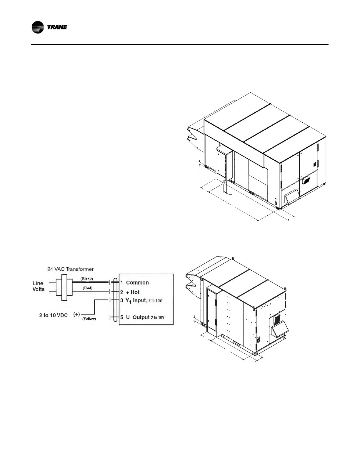
Hot Water Control Valve Wiring
1. Mount the factory-provided water valve on the return line of
the hot water coil.
2. Ensure the valve is set to normally open.
3. Run the 16 gauge black wire from TNS 2 to Input 1 of the
actuator.
4. Run the 16 gauge red wire from TNS 2 to Input 2 of the
actuator.
5. Run the 16 gauge yellow wire from AO1 from the UC600 to
Input 3 of the actuator.
Note: The actuator valve will be open with a 0 percent call
for heat.
Chilled Water Connection Size and
Location
Verify that the power supply complies with the unit
nameplate specifications.
Inspect all control panel components; tighten any loose
connections.
Connect properly sized and protected power supply
wiring to a field-supplied/-installed disconnect switch and
to the main power terminal block (HTB1) in the unit control
panel.
Connect properly-sized earth ground.
Figure 117. Hot water control valve wiring
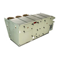
Figure 118. OAB and OAG chilled water cooling pipe-
chase connections
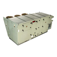
Figure 119. OAK and OAND chilled water cooling pipe-
chase connections
 Loading...