Installation
OAU-SVX007A-EN 77
Filter Installation
The filter rack is accessible through the evaporator coil
compartment door. Filter type, size, and quantity are
determined by selected filter option and unit size.
Note: Do not operate the unit without filters.
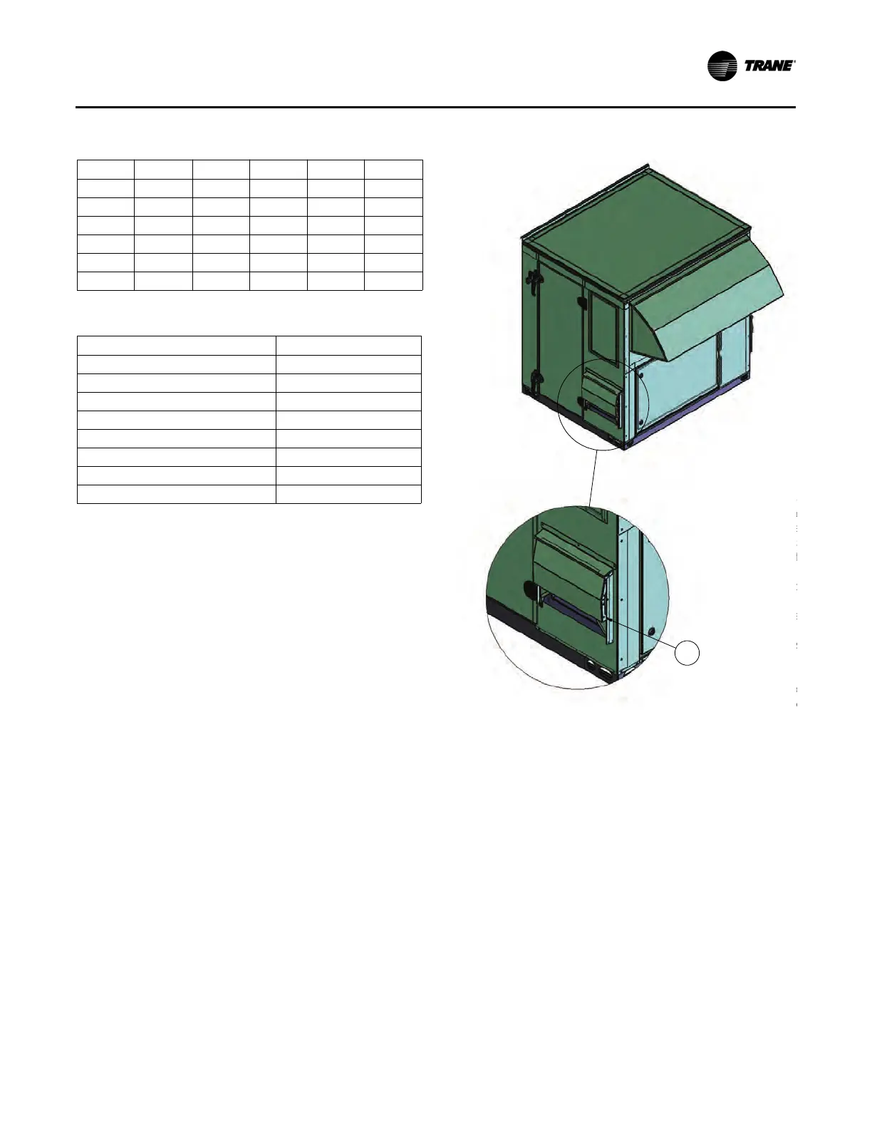
Opening the Collapsed Exhaust Damper
Hood
The drawings shown in this section are for one cabinet. Other
cabinets may have a different appearance, but the process
remains the same.
1. To release the damper hood, remove the hex head sheet
metal screws (one per side) shown in DETAIL A (see
Figure 120) and marked by arrow (1).
2. Lift the hood upward and rotate the side panels outward
while holding the top up.
3. As shown in DETAIL B (see Figure 121) and marked by
arrow (2), secure the side panels to the top of the hood
using (8) hex head sheet metal screws, provided with the
unit, through the pre-punched holes in the top and side
panels (four screws per side).
4. Repeat these steps for the remaining damper hood, if
applicable.
Table 9. Chilled water pipe chase location (in.)
Unit A B C D E
OAB 61.25 12.00 10.00 3.00 3.000
OAG 79.75 12.50 10.00 3.00 4.125
OAK 63.84 19.50 11.00 5.00 NA
OAND 93.93 20.64 11.00 5.00 NA
OAD 64.25 30.00 18.00 3.50 NA
OANG 92.64 30.00 18.00 2.81 NA
Table 10. Chilled water connection size (MPT-in.)
Unit Size MPT-in.
OAB 3–9 tons 2.0
OAG 10–30 tons 2.0
OAK 12–30 tons 2.5
OAND 30-60 tons 3.0
OAD, 4-row 1.5
OAD, 6-row 2.0
OANG, 4-row 2.5
OANG, 6-row 3.0
Figure 120. Powered exhaust damper hood, collapsed
'(7$,/$
6&$/(
7RUH
KH[KH
VLGHV
/LIWW
VLGHS
WRSXS
$VV
VHFXUH
KRRG
VFUHZV
WKHSU
VLGHS
5HS
GDPS
 Loading...