Installation
OAU-SVX007A-EN 79
Verify that the power supply available is compatible with the
unit’s nameplate ratings. The available supply power must be
within 10 percent of the rated voltage stamped on the
nameplate. Use only copper conductors to connect the power
supply to the unit.
Horizon Water Source Heat Pump Field
Connection Instructions
The following instructions illustrate the field connections for
water lines on a typical Horizon™ water source heat pump unit.
Water source heat pump units will be installed on curbs with a
pipe chase section attached (as shown in Figure 123).
1. Open the doors on the water source heat pump cabinet
section to access the coils and the pipe chase panel cover
(see Figure 126 for a view of the pipe chase panel cover
located on the floor of the cabinet section beneath the
center drain pan).
2. Remove the hex head sheet metal screws from the center
drain pan (do not discard) to access the pipe chase panel
cover.
3. Remove the hex head sheet metal screws from the pipe
chase panel cover for access to the pipe chase and discard
the cover.
Note: If water lines will not be entering the cabinet section
through the pipe chase, contractor must field-cut
holes and the pipe chase panel cover can remain
in place.)
4. Cut required holes (size varies depending on unit size and
type of pipe gasket used) in the center drain pan for pipe
entry. Reinstall the center drain pan, insert pipe, and seal
as necessary to prevent water leakage around drain pan/
pipes.
5. Connect the water lines to the NPT male connections
(there is a “water in” and a “water out” connection per unit).
Refer to Table 11, p. 80 for specific water line sizes per
cabinet and tonnage.
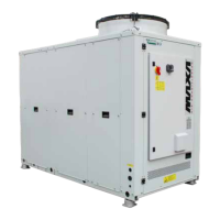
The “water out” line will contain a factory installed ball valve
with actuator. See Figure 127, p. 80 for details (coil size and
style will vary depending on the tonnage of each unit).
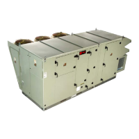
Figure 123. Typical water source heat pump cabinet
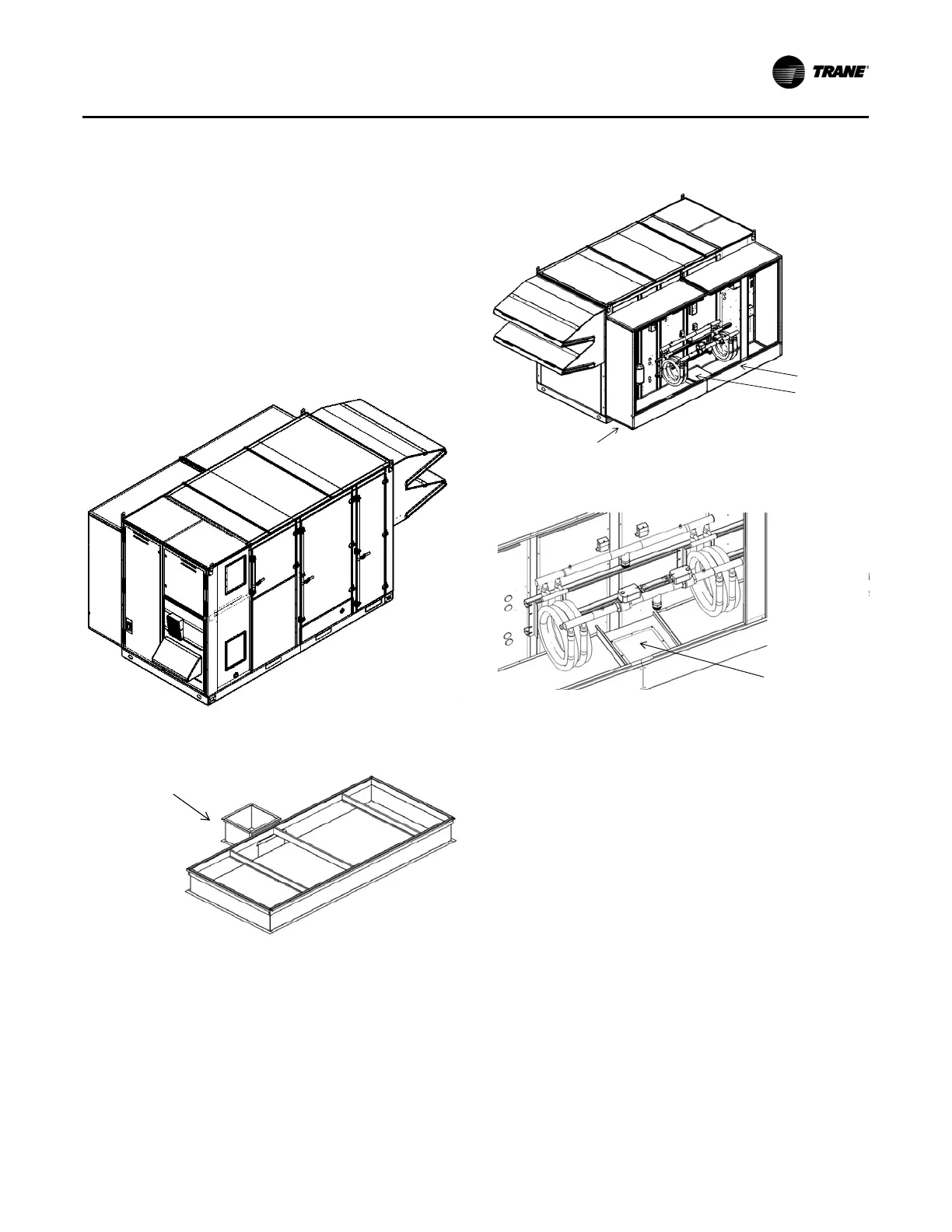
Figure 124. Typical water source heat pump unit curb
PipeChase
SectionofCurb
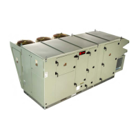
Figure 125. Rear isometric view (doors hidden for
clarity)
Figure 126. Pipe chase panel cover
Figure3
RearIsometricView(DoorsHidden
forClarity)
WaterͲSourceHeatPump
CabinetSection
WaterͲSourceHeat
PumpCoilLocation
CenterDrainPan
PipeChasePanelCover
Fi
PipeChas
 Loading...