1.4. Mounting Instructions
Front Tilted
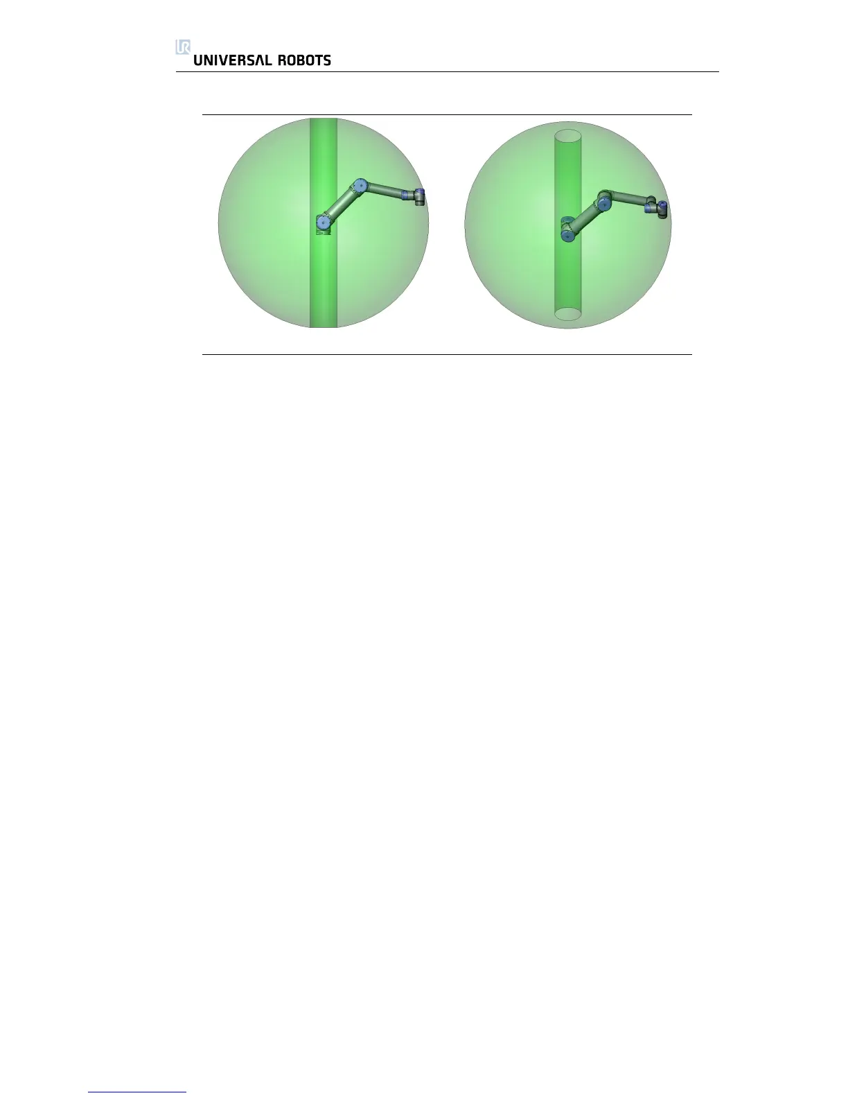
Figure 1.2: The workspace of the robot. The robot can work in an approxi-
mate sphere (Ø260cm) around the base, except for a cylindrical
volume directly above and directly below the robot base.
1.4 Mounting Instructions
The robot consists essentially of six robot joints and two aluminum tubes, con-
necting the robot’s base with the robot’s tool. The robot is built so that the tool
can be translated and rotated within the robot’s workspace. The next subsec-
tions describes the basic things to know when mounting the different parts of
the robot system.
1.4.1 The Workspace of the Robot
The workspace of the UR10 robot extends to 1300 mm from the base joint. The
workspace of the robot is shown in figure 1.2. It is important to consider the
cylindrical volume directly above and directly below the robot base when a
mounting place for the robot is chosen. Moving the tool close to the cylindrical
volume should be avoided if possible, because it causes the robot joints to move
fast even though the tool is moving slowly.
1.4.2 Mounting the Robot
The robot is mounted using 4 M8 bolts, using the four 8.5mm holes on the robot’s
base. It is recommended to tighten these bolts with 20 Nm torque. If very ac-
curate repositioning of the robot is desired, two Ø8 holes are provided for use
with a pin. Also an accurate base counterpart can be purchased as accessory.
Figure 1.3 shows where to drill holes and mount the screws.
1.4.3 Mounting the Tool
The robot tool flange has four holes for attaching a tool to the robot. A drawing
of the tool flange is shown in figure 1.4.
All Rights Reserved
10 UR10

 Loading...


