EasyManuals Logo
Home>Universal Robots>Robotics>UR10

Universal Robots UR10 User Manual

Universal Robots UR10
58 pages
To Next Page IconTo Next Page
To Previous Page IconTo Previous Page
Page #23 background imageLoading...
Page #23 background image
2.4. Controller I/O
Load Controlled by Digital Output, External Power
LO AD
GND GND
DO0 DO1
GND GND GND GND
DO2 DO3 DO4 DO5
GND GND
DO6 DO7
GND GND
24V 24V DO0
24V
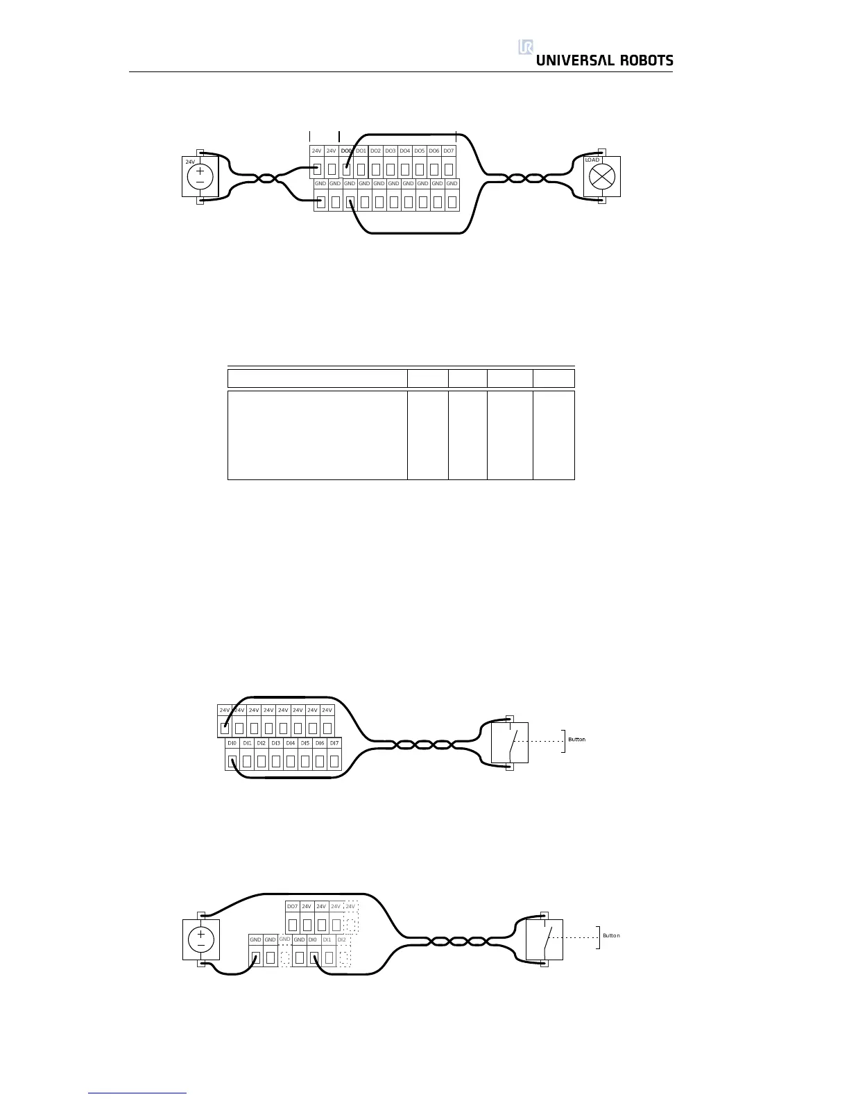
If the available current from the internal power supply is not enough, simply use
an external power supply, as shown above.
2.4.2 Digital Inputs
Parameter Min Typ Max Unit
Input voltage -30 - 30 V
Input guaranteed OFF if -30 - 7 V
Input guaranteed ON if 10 - 30 V
Guaranteed OFF if 0 - 5 mA
ON Current (10-30V) 6 - 10 mA
The digital inputs are implemented as pnp which means that they are ac-
tive when voltage is applied to them. The inputs can be used to read buttons,
sensors or for communication with other PLC systems. The inputs are compliant
with all three types of digital inputs defined in IEC 61131-2 and EN 61131-2, which
means that they will work together with all types of digital outputs defined in the
same standards.
Technical specifications of the digital inputs are shown below.
Digital Input, Simple Button
The above example shows how to connect a simple button or switch.
Digital Input, Simple Button, External Power
GND GND
DO7 24V
GND
GND
DI0 DI1 DI2
24V 24V 24V
Button
The above illustration shows how to connect a button using an external power
source.
All Rights Reserved
23 UR10

Table of Contents

Other manuals for Universal Robots UR10

Questions and Answers:

Question and Answer IconNeed help?

Do you have a question about the Universal Robots UR10 and is the answer not in the manual?

Universal Robots UR10 Specifications

General IconGeneral
BrandUniversal Robots
ModelUR10
CategoryRobotics
LanguageEnglish

Related product manuals