2.5. Tool I/O
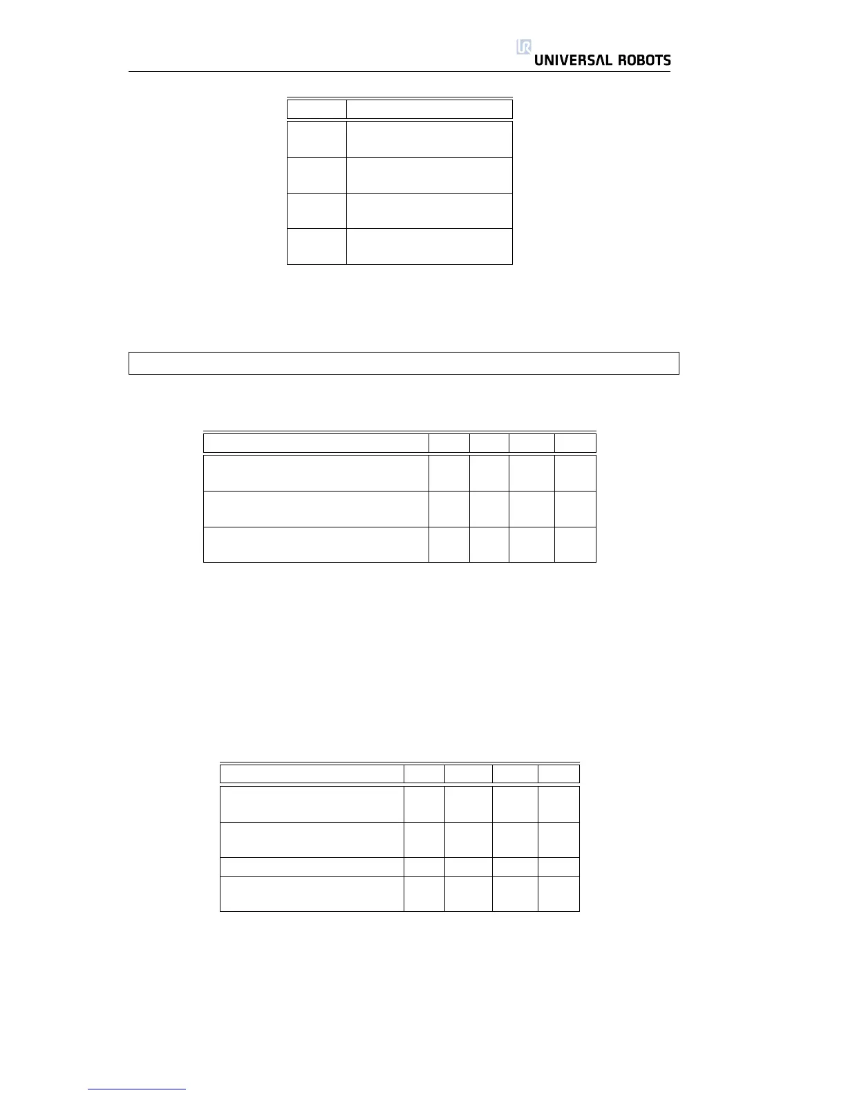
Color Signal
Red 0V (GND)
Gray 0V/12V/24V (POWER)
Blue Digital output 8 (DO8)
Pink Digital output 9 (DO9)
Yellow Digital input 8 (DI8)
Green Digital input 9 (DI9)
White Analog input 2 (AI2)
Brown Analog input 3 (AI3)
This connector provides power and control signals for basic grippers and sen-
sors, which may be present on a specific robot tool. This connector can be used
to reduce wiring between the tool and the control box. The connector is a stan-
dard Lumberg RSMEDG8, which mates with a cable named RKMV 8-354.
Note that the tool flange is connected to GND (same as the red wire).
Internal Power Supply Specifications
Parameter Min Typ Max Unit
Supply voltage in 24V mode TBD 24 TBD V
Supply voltage in 12V mode TBD 12 TBD V
Supply current in both modes - - 600 mA
Short-circuit current protection - 650 - mA
Capacitive load - - TBD uF
Inductive load - - TBD uH
The available power supply can be set to either 0V, 12V or 24V at the I/O tab
in the graphical user interface. Take care when using 12V, since an error made
by the programmer can cause a voltage change to 24V, which might damage
the equipment and even cause a fire.
The internal control system will generate an error to the robot log if the current
exceeds its limit. The different I/Os at the tool is described in the following three
subsections.
2.5.1 Digital Outputs
Parameter Min Typ Max Unit
Voltage when open -0.5 - 26 V
Voltage when sinking 1A - 0.05 0.20 V
Current when sinking 0 - 1 A
Current through GND - - 1 A
Switch time - 1000 - us
Capacitive load - - TBD uF
Inductive load - - TBD uH
The digital outputs are implemented so that they can only sink to GND (0V)
and not source current. When a digital output is activated, the corresponding
connection is driven to GND, and when it is deactivated, the corresponding
connection is open (open-collector/open-drain). The primary difference be-
tween the digital outputs inside the control box and those in the tool is the re-
duced current due to the small connector.
All Rights Reserved
27 UR10

 Loading...


