2.5. Tool I/O
Note that the digital outputs in the tool are not current limited and overriding
the specified data can cause permanent damage.
To illustrate clearly how easy it is to use digital outputs, a simple example is
shown.
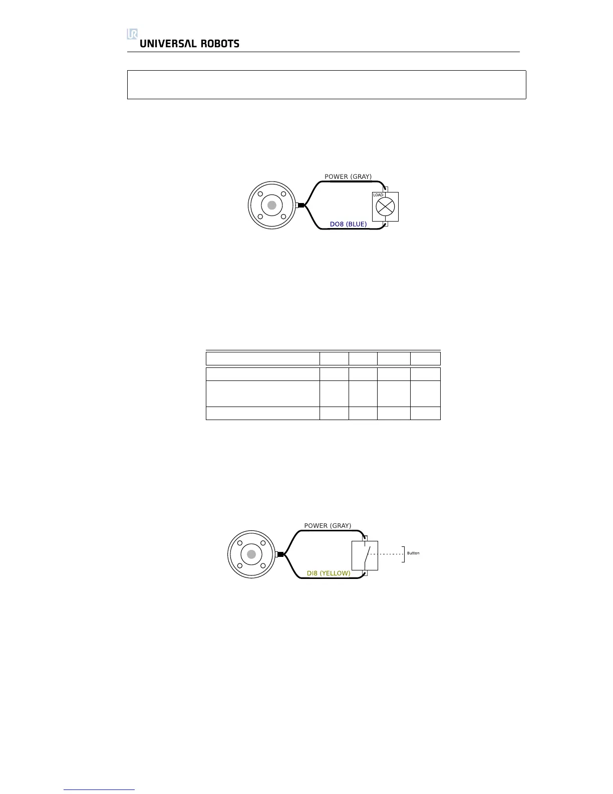
Using Digital Outputs
This example illustrates how to turn on a load, when using the internal 12V
or 24V power supply. Remember that you have to define the output voltage at
the I/O tab. Keep in mind that there is voltage between the POWER connection
and the shield/ground, even when the load is turned off.
2.5.2 Digital Inputs
Parameter Min Typ Max Unit
Input voltage -0.5 - 26 V
Logical low voltage - - 2.0 V
Logical high voltage 5.5 - - V
Input resistance - 47k - Ω
The digital inputs are implemented with weak pull-down resistors. This means
that a floating input will always read low. The digital inputs at the tool are imple-
mented in the same way as the digital inputs inside the control box.
Using Digital Inputs
The above example shows how to connect a simple button or switch.
2.5.3 Analog Inputs
The analog inputs at the tool are very different from those inside the control
box. The first thing to notice is that they are non-differential, which is a draw-
back compared to the analog inputs at the controller I/O. The second thing to
notice is that the tool analog inputs have current mode functionality, which is an
advantage compared with the controller I/O. The analog inputs can be set to
different input ranges, which are implemented in different ways, and therefore
can have different offset and gain errors.
All Rights Reserved
28 UR10
 Loading...


