2.4. Controller I/O
Parameter Min Typ Max Unit
24V Voltage tolerance -15% - +20% -
Current available from 24V supply - - 1.2∗ A
Overload protection - 1.4 - A
[TA-TB][A↑][R↑] Voltage 10.5 12 12.5 V
[TA-TB][A↑][R↑] Current - - 120 mA
[TA-TB][A↑][R↑] Current protection - 400 - mA
[SA-SB] Input voltage -30 - 30 V
[SA-SB] Guaranteed OFF if -30 - 7 V
[SA-SB] Guaranteed ON if 10 - 30 V
[SA-SB] Guaranteed OFF if 0 - 3 mA
[SA-SB] ON Current (10-30V) 7 - 14 mA
[A↓][R↓] Input voltage -30 - 30 V
[A↓][R↓] Input guaranteed OFF if -30 - 7 V
[A↓][R↓] Input guaranteed ON if 10 - 30 V
[A↓][R↓] Guaranteed OFF if 0 - 5 mA
[A↓][R↓] ON Current (10-30V) 6 - 10 mA
The safeguard stop input SA-SB is a potential free input conforming to IEC
60664-1 and EN 60664-1, pollution degree 2, over-voltage category II.
Note that the yellow 24V connections is sourced by the same internal 24V power
supply as the 24V connections of the normal I/O, and that the maximum of 1.2
A is for both power sources together.
2.4 Controller I/O
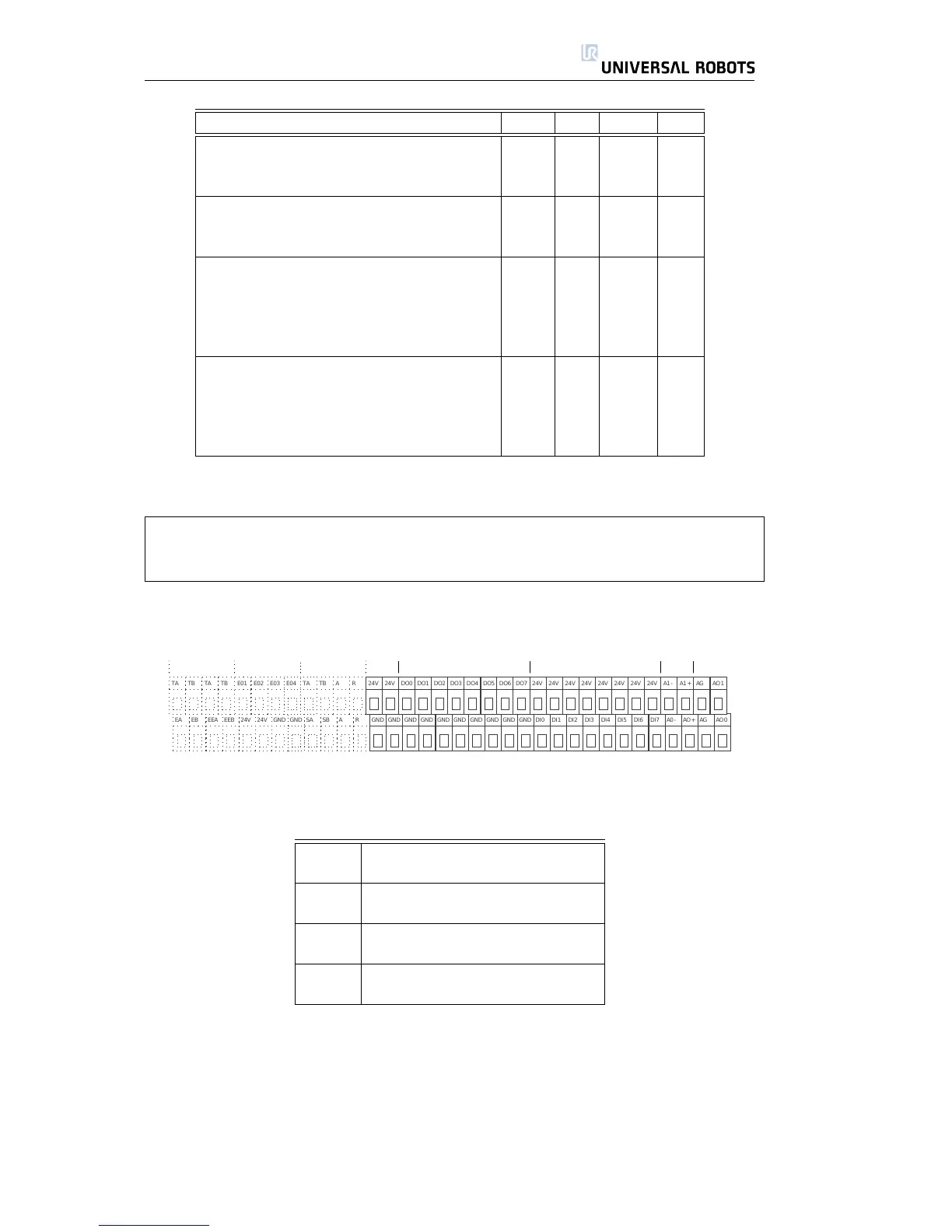
Inside the control box there is a panel of screw terminals with various I/O
parts, as shown above. The rightmost part of this panel is general purpose I/O.
[24V] +24V supply connection
[GND] 0V supply connection
[DOx] Digital output number x
[DIx] Digital input number x
[AOx] Analog output number x plus
[AG] Analog output GND
[Ax+] Analog input number x plus
[Ax-] Analog input number x minus
The I/O panel in the control box has 8 digital and 2 analog inputs, 8 digital
and 2 analog outputs, and a built in 24V power supply. Digital inputs and outputs
are pnp technology and constructed in compliance with IEC 61131-2 and EN
61131-2. 24V and GND can be used as input for the I/O module or output as a
24V power supply. When the control box is booting it checks if voltage is applied
to the 24V connection from an external power supply, and if not, it automatically
connects the internal 24V power supply.
All Rights Reserved
21 UR10

 Loading...


