2.4. Controller I/O
Electrical specifications of the internal power supply
Parameter Min Typ Max Unit
Internal 24V voltage tolerance -15% - +20% -
Current from internal 24V supply - - 1.2∗ A
Overload protection - 1.4 - A
External power supply voltage 10 - 30 V
Note that the safeguard (yellow) 24V connections are sourced by the same
internal 24V power supply as the 24V connections of the normal I/O, and that
the maximum of 1.2 A is for both power sources together.
If the current load of the internal 24V power supply is exceeded, an error
message is printed on the log screen. The power supply will automatically try to
recover after a few seconds.
2.4.1 Digital Outputs
Parameter Min Typ Max Unit
Source current per output 0 - 2 A
Source current all outputs together 0 - 4 A
Voltage drop when ON 0 - 0.2 V
Leakage current when OFF 0 0 - 0.1 mA
The outputs can be used to drive equipment directly e.g. pneumatic relays
or they can be used for communication with other PLC systems. The outputs
are constructed in compliance with all three types of digital inputs defined in
IEC 61131-2 and EN 61131-2, and with all requirements for digital outputs of the
same standards.
All digital outputs can be disabled automatically when a program is stopped,
by using the check box “Always low at program stop” on the I/O Name screen
(see the PolyScope manual). In this mode, the output is always low when a
program is not running.
The digital outputs are not current limited and overriding the specified data
can cause permanent damage. However, it is not possible to damage the out-
puts if the internal 24V power supply is used due to its current protection.
Note that the control box and the metal shields are connected to GND. Never
send I/O current through the shields or earth connections.
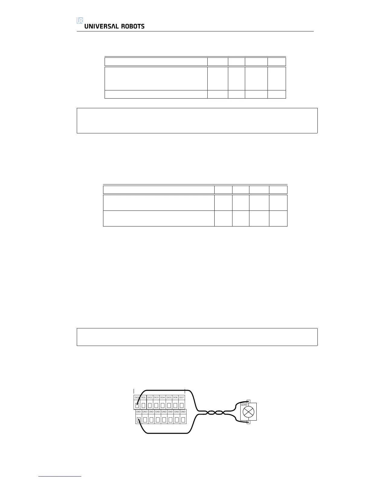
The next subsections show some simple examples of how the digital outputs
could be used.
Load Controlled by Digital Output

 Loading...


