A.3. GUI
high under the condition that the electrical supervision signal of the mould area
(possible with use of light guard, as explained above), and the MAF signal from
the software are both high. The MAF signal from software can be controlled by
the respective button. The emergency stop signal from the machine indicates
whether the IMM is emergency stopped. The Safeguard Open input shows the
state of the ”Safety devices” signals specified in the euromap67 standard.
Status
The operation mode of the robot and the IMM can be controlled/viewed (these
signals are also used in the program structures). The bars showing voltage and
current consumption represent the values delivered to the IMM and possibly a
light guard by the euromap67 module.
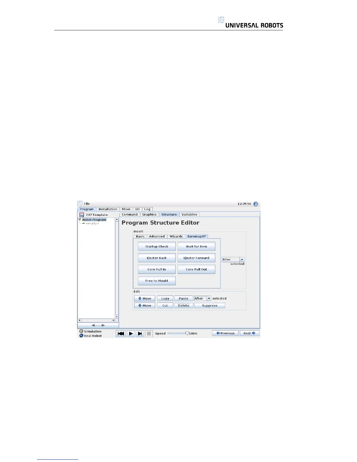
A.3.3 Program structure functionality
There are seven program structures, which can be selected from the Structure
tab on the program screen. These structures will be available after the eu-
rompa67 interface has been properly installed (as explained in section A.4). An
example of their use, can be seen in the euromap67 program template.
The structures are all made to achieve a proper and safe interaction with the
IMM, and therefore they all include tests that certain signals are set correctly.
Also, they may set more than one output to enable only one action.
When a program structure is inserted into a robot program, it can be cus-
tomized by selecting the structure in the program, and then clicking on the
Command tab. All program structures consist of a number of steps. Most of
the steps are enabled per default, and some cannot be disabled because they
are essential to the structure intention. The Test steps make the program stop if
the test condition is not met. Both the state of inputs and outputs are testable.
Set output steps set a specified output to either high or low. Wait until steps are
typically used for waiting until a movement has been finished before continuing
with further steps and following program nodes.
All Rights Reserved
49 UR10

 Loading...


