Appendix A
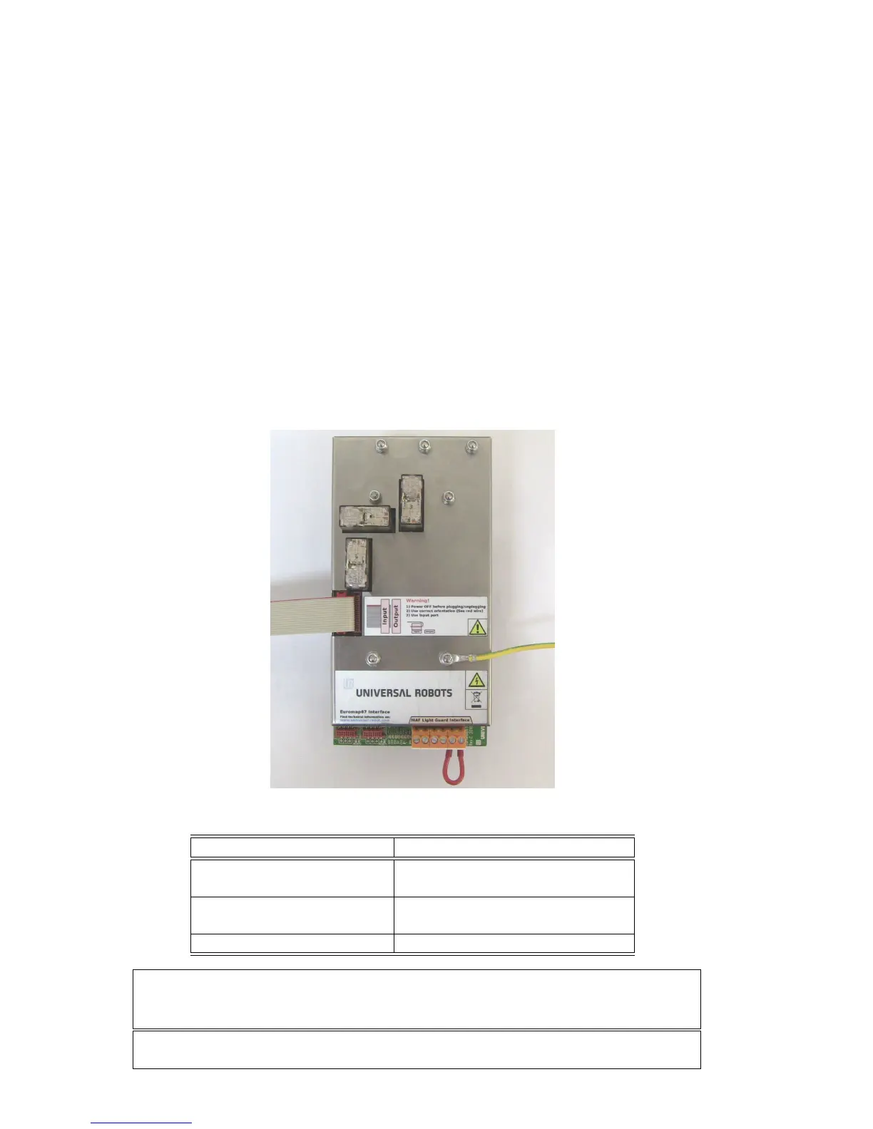
Euromap67 Interface
A.1 Introduction
This manual is intended for the integrator. It contains important information re-
garding integration, programming, understanding and debugging.
Abbreviations used in this document are explained below.
Abbreviation Meaning
UR Universal Robots
CB Controller Box
IMM Injection Moulding Machine
MAF Moulding Area Free
A, B, C, ZA, ZB and ZC Signals inside euromap67 cable
WARNING: An IMM can use up to 250V on some of its signals. Do not connect
an IMM to the euromap67 interface if it is not properly installed in a controller
box; including all mandatory ground connections.
NOTE: Euromap67 is only supported on controller boxes produced after medio
March 2011.
43

 Loading...


