Inside the control box there is a panel of screw terminals. The leftmost part,
in black above, is the safety interface. The safety interface can be used to
connect the robot to other machinery or protective equipment, to make sure
the robots stops in certain situations.
The safety interface is comprised of two parts; the emergency stop interface
and the safeguard stop interface, further described in the following sections.
The table below summarizes their differences:
Emergency Stop Safeguard Stop
Robot stops moving Yes Yes
Initiations Manual Manual or automatic
Program execution Stops Pauses
Brakes Active Not active
Motor power Off Limited
Reset Manual Automatic or manual
Use frequency Infrequent Every cycle to infrequent
Requires re-initialization Brake release only No
EN/IEC 60204 and NFPA 79 Stop category 1 Stop category 2
Performance level ISO 13849-1 PLd ISO 13849-1 PLd
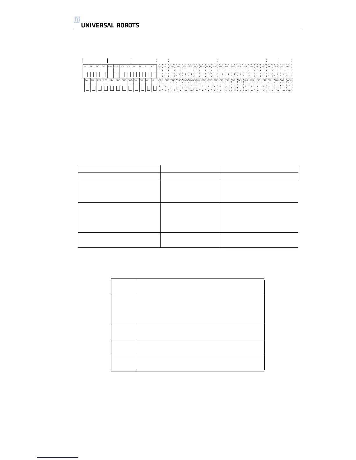
2.3.1 The Emergency Stop Interface
[TA] Test Output A
[TB] Test Output B
[EO1] Emergency Stop Output Connection 1
[EO2] Emergency Stop Output Connection 2
[EO3] Emergency Stop Output Connection 3
[EO4] Emergency Stop Output Connection 4
[EA] Robot Emergency Stop Input A (Positive)
[EB] Robot Emergency Stop Input B (Negative)
[EEA] External Emergency Stop Input A (Positive)
[EEB] External Emergency Stop B (Negative)
[24V] +24V supply connection for safety devices
[GND] 0V supply connection for safety devices
The Emergency Stop interface has two inputs, the Robot Emergency Stop input
and the External Emergency Stop input. Each input is doubled for redundancy
due to the safety performance level d.
The Robot Emergency Stop interface will stop the robot, and will set the Emer-
gency Stop output, intended for use by safety equipment near the robot. The
External Emergency Stop will also stop the robot, but will not affect the Emer-
gency Stop output, and is only intended for connecting to other machines.
All Rights Reserved
16 UR10

 Loading...


