112 www.xilinx.com RocketIO™ Transceiver User Guide
UG024 (v3.0) February 22, 2007
Chapter 3: Analog Design Considerations
R
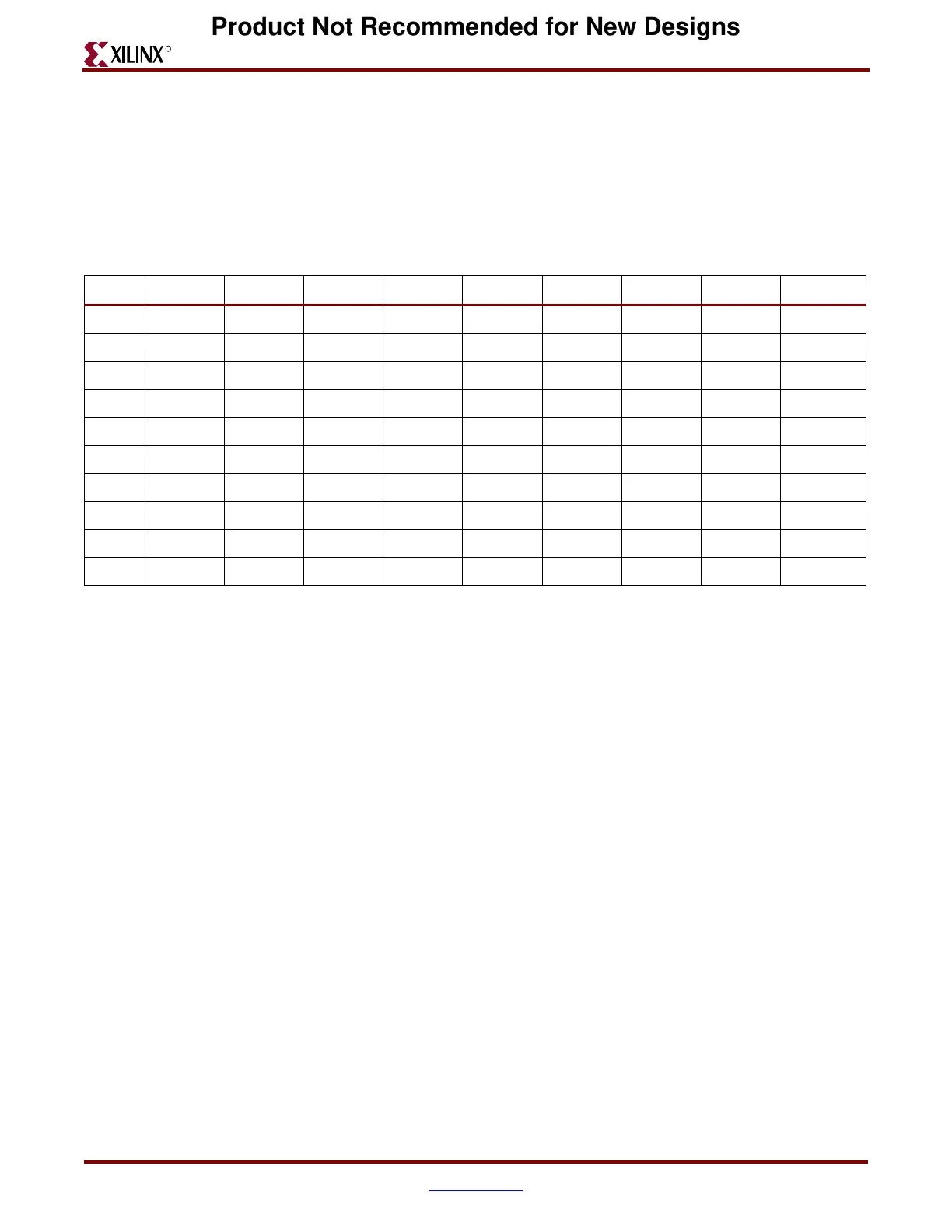
cases, as ferrite beads are not included inside the package in any device. Table boxes
labeled “External” denote a device for which the user must provide power filtering
capacitors externally on the PCB; those labeled “Internal” denote a device that contains all
necessary 0.22 μF capacitors for RocketIO power pins. Table boxes that say “No MGTs”
denote a device that does not have any RocketIO transceivers.
For devices that do not contain filtering capacitors in their package, the 0.22 μF capacitors
must be placed within 1 cm of the pins they are connected to.
Figure 3-9, Figure 3-10, and Figure 3-11 show example layouts of the power filtering
network for four transceivers (in one case in a package with internal capacitors, in another
case in a package with external capacitors).
The device in Figure 3-9 is in an FF672 package, which has eight transceivers total—four on
the top edge (rows A/B), and four on the bottom edge (rows AE/AF). This device contains
internal capacitors, so it is only necessary to have ferrite beads on the PCB. Figure 3-9
shows the bottom PCB layer, with lands for ferrite beads of the VTTX, VTRX,
Table 3-7: Device and Package Combinations showing Devices with RocketIO Power Filtering Capacitors
Internal to the Package and Externally Mounted on the PCB
XC2VP2 XC2VP4 XC2VP7 XC2VP20 XC2VP30 XC2VP40 XC2VP50 XC2VP70 XC2VP100
FG256 External External
FG456 External External External
FF672 Internal Internal Internal
FG676 External External External
FF896 Internal Internal Internal
FF1152 Internal Internal Internal Internal
FF1148 No MGTs No MGTs
FF1517 Internal Internal Internal
FF1704 Internal Internal
FF1696 No MGTs
Product Not Recommended for New Designs
 Loading...
