RXUSRCLK2 is the main synchronizaon clock for all signals into the RX side of the GTM
transceiver. Most signals into the RX side of the GTM transceiver are sampled on the posive
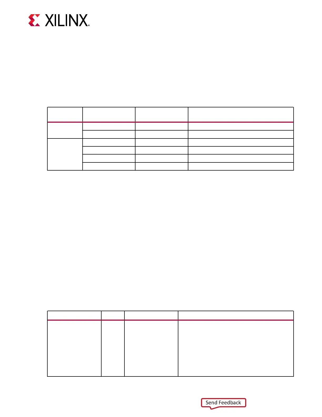
edge of RXUSRCLK2. RXUSRCLK2 and RXUSRCLK have a xed-rate relaonship based on the
RX_DATA_WIDTH and RX_INT_DATA_WIDTH sengs. The following table shows the
relaonship between RXUSRCLK2 and RXUSRCLK per the RX_DATA_WIDTH and
RX_INT_DATA_WIDTH values.
Table 70: RXUSRCLK2 Frequency Relationship to RXUSRCLK
Encoding RX Data Width
RX Internal
Datapath
RXUSRCLK2 Frequency
NRZ 64 64 F
RXUSRCLK2
= F
RXUSRCLK
128 64 F
RXUSRCLK2
= F
RXUSRCLK
/2
PAM4 80 80 F
RXUSRCLK2
= F
RXUSRCLK
160 80 F
RXUSRCLK2
= F
RXUSRCLK
/2
128 128 F
RXUSRCLK2
= F
RXUSRCLK
256 128 F
RXUSRCLK2
= F
RXUSRCLK
/2
These rules about the relaonships between clocks must be observed for RXUSRCLK and
RXUSRCLK2:
• RXUSRCLK and RXUSRCLK2 must be posive-edge aligned, with as lile skew as possible
between them. As a result, low-skew clock resources (BUFG_GTs) must be used to drive
RXUSRCLK and RXUSRCLK2.
• If the channel is congured so that the same oscillator drives the reference clock for the
transmier and the receiver, TXPROGDIVCLK can be used to drive RXUSRCLK and
RXUSRCLK2 in the same way that they are used to drive TXUSRCLK and TXUSRCLK2.
• If separate oscillators are driving the reference clocks for the transmier and receiver on the
channel, RXUSRCLK and RXUSRCLK2 must be driven by RXPROGDIVCLK.
Ports and Attributes
The following table denes the TX interface ports.
Table 71: RX Interface Ports
Port Dir Clock Domain Description
RXDATA[255:0] Out RXUSRCLK2 The bus for receiving data. The width of this port is
equal to RX data width selection. RX data width
selection:
64: RXDATA[63:0]
80: RXDATA[79:0]
128: RXDATA[127:0]
160: RXDATA[159:0]
256: RXDATA[255:0]
Chapter 4: Receiver
UG581 (v1.0) January 4, 2019 www.xilinx.com
Virtex UltraScale+ GTM Transceivers 115
 Loading...
