Page 103FT-
991
The
contains ninety-nine regular memories, labeled “
01
” through “
99
”, nine special programmed band edge
memory pairs, labeled “
P-1L
P-1U
” through “
P-9L
P-9U
”, and ve QMB
(
Quick Memory Bank
)
memories. Each mem-
ory stores various settings, in addition to the VFO-A frequency and mode, but also stores the various settings shown be-
low. By default, the 99 regular memories are contained in one group; however, they can be arranged in up to six separate
groups, if desired.
The
memory channels store the following
data
(
not just the operating frequency
)
:
VFO-A Frequency
VFO-A Mode
Clarier status and its Oset Frequency
IPO status
Attenuator status
Noise Blanker status
IF SHIFT and WIDTH status
CONTOUR status and its Peak Frequency
DSP Noise Reduction
(
DNR
)
status and its
Reduction algorithm selection.
DSP Notch lter
(
NOTCH
)
status
NAR bandwidth status
DSP Auto Notch lter
(
DNF
)
status
Repeater Shift Direction
CTCSS Tone information
(
CTCSS Encode,
Decode ON/OFF; Tone Frequency
)
DCS information
(
DCS On/O, DCS Code
)
01
97
P-7L/7U
P-6L/6U
P-5L/5U
P-4L/4U
02
98
P-8L/8U
03
99
P-9L/9U
P-1L/1U
P-2L/2U
P-3L/3U
(
)
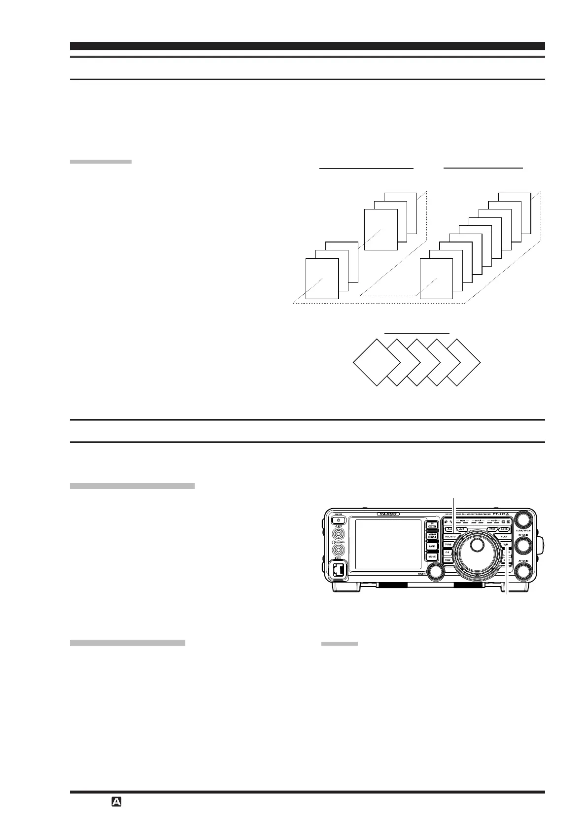
The Quick Memory Bank consists of ve memories independent from the regular and PMS memories. The QMB mem-
ories can quickly store operating parameters for later recall.
1. Tune to the desired frequency on VFO-A.
2. Press and hold the
button for one second.
The “beep” will confirm that the VFO-A contents
have been written to the currently available QMB
memory.
Repeated one second presses of the
but-
ton will write the VFO-A contents to successive QMB
memories.
Once all ve QMB memories have data on them, previ-
ous data will be over-written on a rst-in, rst-out basis.
1. Press the
button briefly. The current
QMB channel data will be shown on the frequency
display area. The “
” icon will also appear and
the Memory Mode indicators in the LED indicators
area will illuminate.
2. Repeated brief presses of the
button will
toggle through the QMB channels.
3. Press the
button to return to the VFO or Memo-
ry mode.
RCL/STO Button
V/M Button
Rotating the Main Tuning Dial knob, or changing the
operating mode, will place the transceiver in the “Mem-
ory Tune” mode, which is a temporary “pseudo-VFO”
method of tuning o of a stored memory channel. If you
do not over-write the contents of the current memory
channel, the original contents will not be disturbed by
the initiation of Memory Tune operation.