Page 18 F
T-991
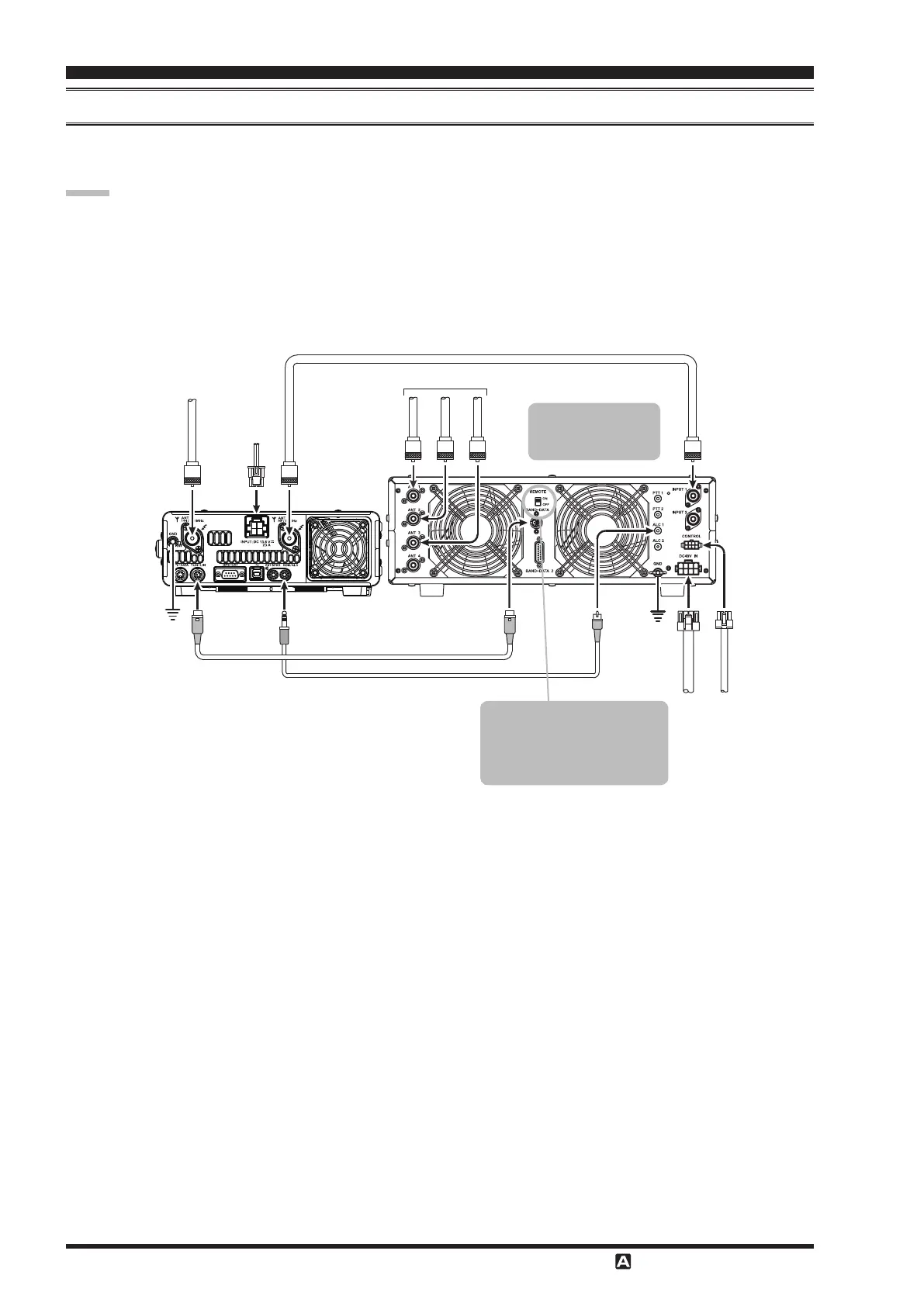
Be sure that both the
and
are turned o, and then follow the installation recommendations contained
in the illustration.
Refer to the
Operating Manual for details regarding amplier operation.
Do not attempt to connect or disconnect coaxial cables when your hands are wet.
Set the Menu item “
141 TUNER SELECT
” to “
LAMP
”.
Since the ALC cable is connected to the
jack, the optional
cannot be connected.
DC 13.8 V
CT-58 ALC Cable (Option)
CT-58 Band Data Cable (Option)
144/430MHz Antenna
HF/50MHz Antenna
Coaxial Cable (50Ω)
Connect to “INPUT 1” of the VL-1000
INPUT
BAND-DATA 1
ALC 1
TUN/LIN
REM/ALC
GND
GND
VP-1000
VP-1000
CONTROL
DC 48V IN
ANT 1
ANT 2
ANT 3
INPUT 1
ANT
144/430MHz
ANT
HF/50MHz
To link the and
Power switches, set the
VL-1000 REMOTE switch to
the “ON” position.
Set the front panel’s
switch to the
“INPUT1”.
 Loading...