Page 143FT-
991
(
)
The
makes use of the control circuitry built into the transceiver, which allows the operator to control and monitor
automatic operation of the
, which mounts near the antenna feedpoint. The
uses specially selected,
thermally stable components, and is housed in a waterproof case to withstand severe environmental conditions with high
reliability.
A carefully-chosen combination of solid-state switching components and high-speed relays allows the
to match
a wide variety of antennas to within a 2:1 SWR on any amateur band frequency
(
160 through 6 meters
)
, typically in less
than eight seconds. Transmitter power required for matching may be as little as 4 - 60 Watts, and matching settings are
automatically stored in memory for instant recall when the same frequency range is selected later.
Please see the
Operating Manual for detailed information.
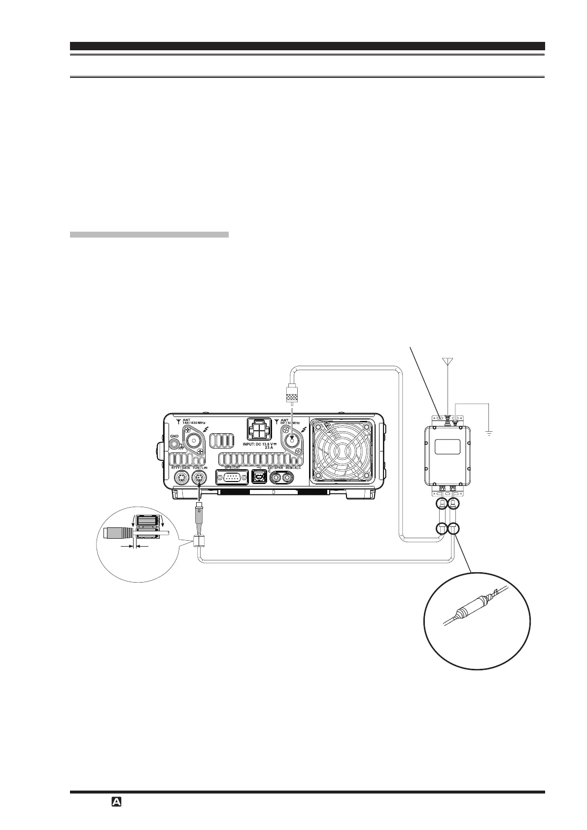
After mounting the
, connect the cables from the
to the ANT and TUNER jacks on the rear panel
of the
Transceiver.
Antenna Cable
(
5 m
)
Control Cable
(
5 m
)
GND
ANT
Antenna Terminal
Install the supplied ferrite
core as close to the con-
nector as possible.
Wrap the ends of the waterproof
cap with the supplied sealing
tape to protect against moisture
ingress.
 Loading...