Mechanical Installation
3
3.4 Panel Cut-Out Dimensions (IP55/UL Type 12 Heatsink External Mounting)
YASKAWA TOEPC71061779E GA800 DRIVE INSTALLATION MANUAL
25
Model
Dimensions mm (in)
W1 W2 W3 W5 H1 H2 H3 H4 A B d1 d2
2070, 2082
4044, 4060
192
(7.56)
192
(7.56)
246
(9.69)
7
(0.28)
371
(14.61)
27
(1.06)
114.5
(4.51)
150
(5.91)
214
(8.43)
319
(12.56)
M6 M5
2110
4075
195
(7.68)
204
(8.03)
265.5
(10.45)
10
(0.39)
385
(15.16)
19.5
(0.77)
112.5
(4.43)
160
(6.30)
224
(8.82)
346
(13.62)
M6 M5
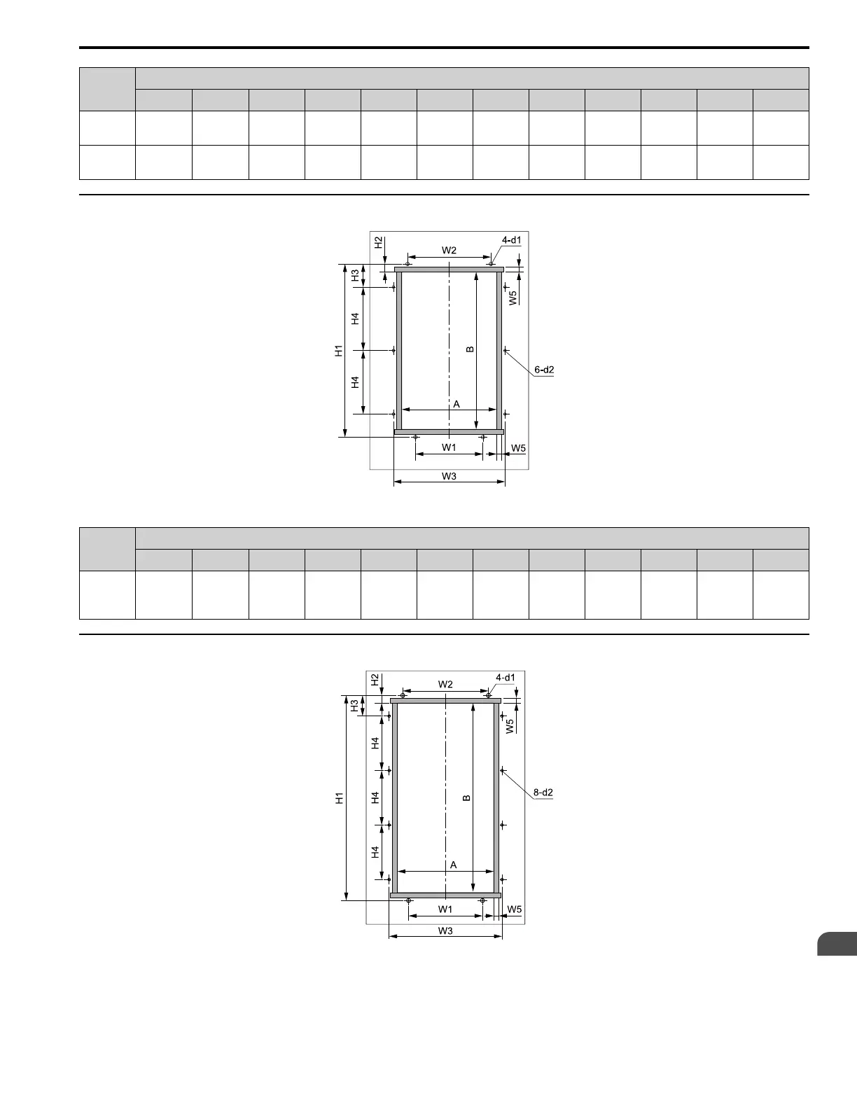
◆ Models 2138, 4089, 4103, T103
Figure 3.8 Panel Cut-Out Dimension Diagram 2
Model
Dimensions mm (in)
W1 W2 W3 W5 H1 H2 H3 H4 A B d1 d2
2138
4089, 4103
T103
170
(6.69)
210
(8.27)
281
(11.06)
7
(0.28)
436
(17.17)
20
(0.79)
58
(2.28)
160
(6.30)
239
(9.41)
396
(15.59)
M6 M5
◆ Models 2169, 2211, 4140, 4168, T140, T168
Figure 3.9 Panel Cut-Out Dimension Diagram 3
 Loading...


