3.7 Installation Procedure
36
YASKAWA TOEPC71061779E GA800 DRIVE INSTALLATION MANUAL
• M10 screws: 17.65 N∙m to 22.56 N∙m (156.22 lbf∙in to 199.67 lbf∙in)
• M12 screws: 31.38 N∙m to 39.23 N∙m (277.74 lbf∙in to 347.22 lbf∙in)
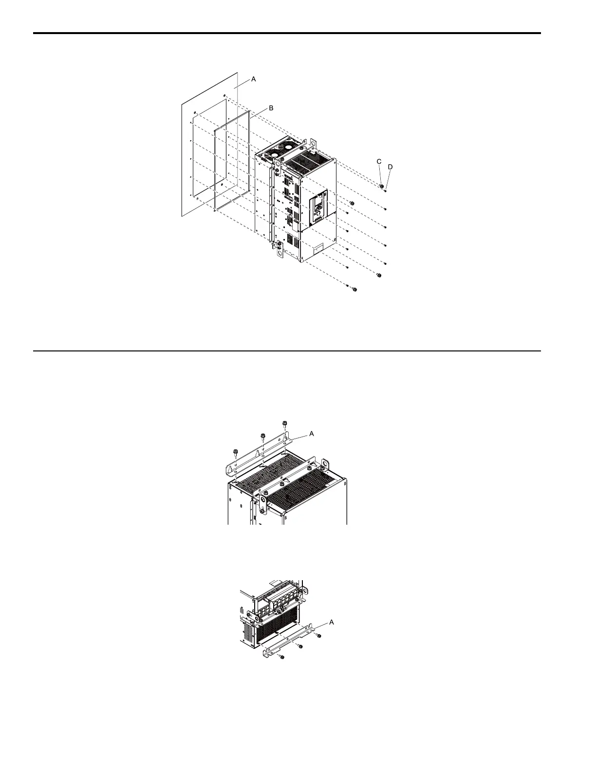
A - Enclosure panel
B - Gaskets
C - M10 screws or M12 screws
D - M5 screws
Figure 3.24 Install the Drive into the Opening of the Enclosure Panel
◆ Install the Drive (Procedure E)
Cut an opening in the enclosure panel before you install the attachment. Refer to Panel Cut-Out Dimensions (IP55/UL
Type 12 Heatsink External Mounting) on page 24 for more information.
1. Remove the shipping attachment from the top of the drive.
A - Shipping attachment
Figure 3.25 Remove the Shipping Attachment
2. Remove the shipping attachment from the bottom of the drive.
A - Shipping attachment
Figure 3.26 Remove the Shipping Attachment
 Loading...


