4-2
IM CW240E
4.1 Precautions for Wiring to
the Measurement Circuit
WARNING
• Before carrying out wiring, be sure to read through 3.3, Connecting Voltage
Probes, and 3.4, Connecting Clamp-on Probes.
• Do not apply an input exceeding the following value to the voltage input
terminals.
Maximum allowable input : 1000 V rms
For measurement category III : 600 V rms
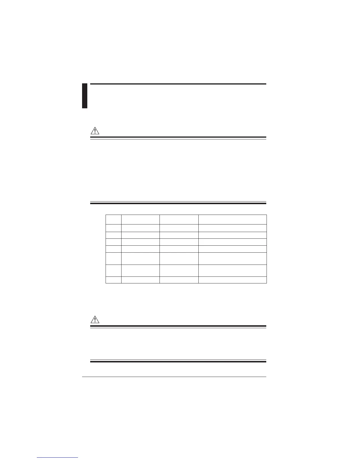
• The maximum allowable input and maximum operating circuit voltage of the
clamp-on probes are as specified in the table below. Do not apply an input
exceeding the relevant value or use the CW240 at a circuit voltage
exceeding it.
96036 2 A 20 A 50 V/CAT.III
96033 50 A 60 A 300 V/CAT.III
96030 200 A 250 A 300 V/CAT.II, 600 V/CAT.II
96031 500 A 625 A 300 V/CAT.II, 600 V/CAT.II
96032 700 A (continuous) 700 A (continuous) 600 V
1000 A (for 5 min) 1000 A (for 5 min)
96034 1000/2000/3000 A 2400 A (continuous) 600 V/CAT.III
3600 A (for 10 min)
96035 300/3000 A 360/360 A 1000 V/CAT.III (area to be measured)
Maximum Operating Circuit Voltage/
Measurement Category
Model Current Rating
Maximum
Allowable Input
SEE ALSO
For more information, see Chapter 17, CW 240 Specifications.
WARNING
• If using an external VT (voltage transformer) or CT (current transformer), make
sure the transformer can sufficiently withstand the voltage to be measured.
• Be careful not to allow the secondary side of CT to become open-circuited
while the CT is being energized. Otherwise, a high voltage may develop on the
secondary side, posing extreme risks.
Chapter 4

 Loading...


