4-23
IM CW240E
Wiring
4
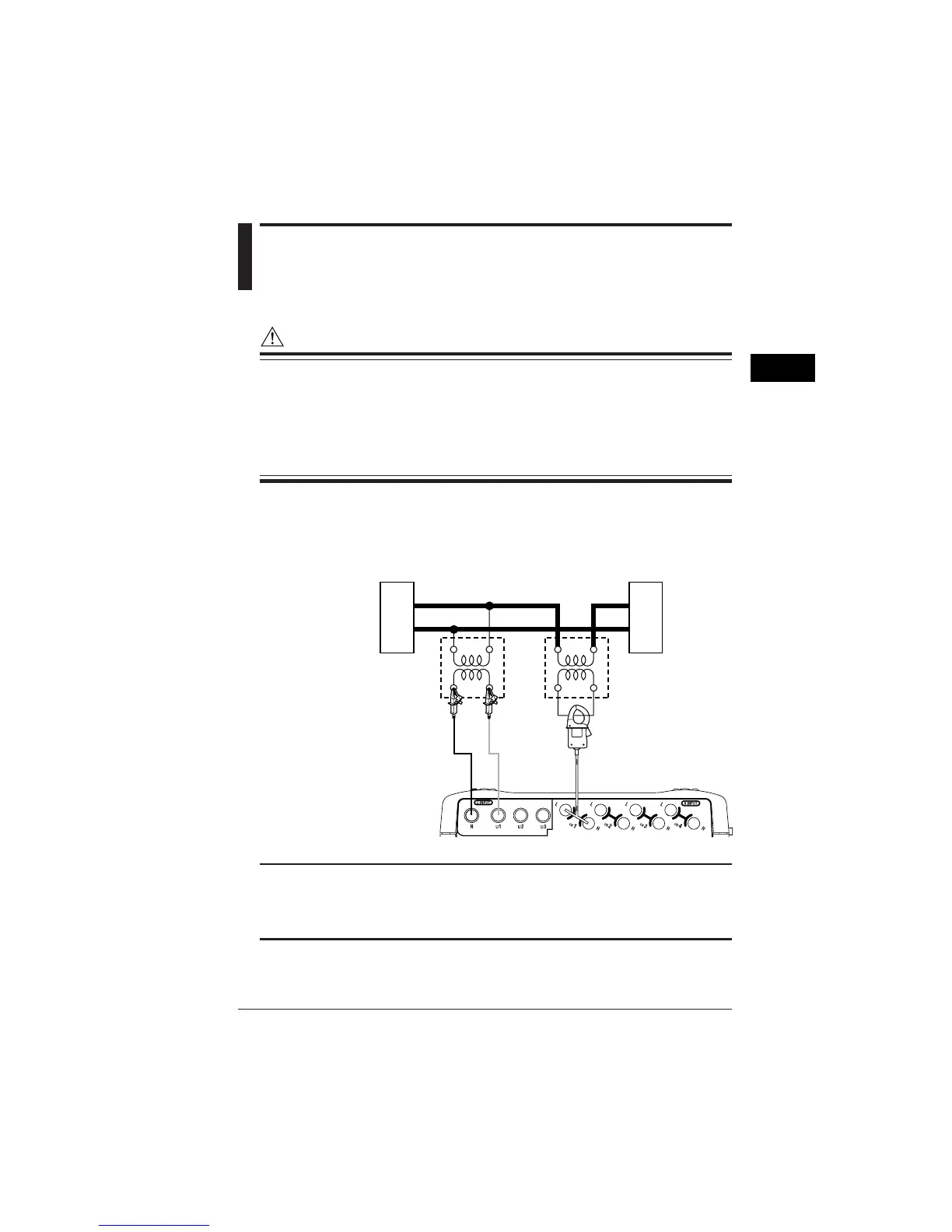
4.6 Wiring the Measurement
Circuit Using External VT/CT
WARNING
• When using an external CT, be careful not to allow the secondary side of the
CT to become open-circuited while the primary side is being energized,
otherwise, a high voltage may develop on the secondary side, posing extreme
risks.
• The current under test flows though the thick lines shown in the figure below.
For these, use wires that have an adequate margin of current-carrying
capacity.
If the maximum voltage or current level of the circuit under test exceeds the
maximum measurement range of the CW240, use an external VT and/or CT.
This strategy enables the measurement of the voltage or current level.
Example of Single-phase 2-wire (1P2W)
Power supply
Load
VT
(voltage transformer)
CT
(current transformer)
1
N
V
v
L
艎
TIP
• If using VT and/or CT, setting the VT ratio and/or CT ratio allows the CW240 to
display the primary-side value.
• When the secondary side of the CT is rated at 5 A, it is recommended that the 96033
(for 50 A) clamp-on probe be used in the 5 A range.
SEE ALSO
For how to set a VT or CT ratio, see 6.2.7, Setting Up VT Ratio and CT Ratio.

 Loading...


