JOHNSON CONTROLS
149
SECTION 7 – UNIT CONTROL CENTER
FORM 150.67-NM2
ISSUE DATE: 01/31/2019
7
R E M O T E U N I T I D
P R O G R A M M E D = X
When communications is required with a BAS or Op-
tiView Panel, individual unit IDs are necessary for
communications with specific chillers on a single RS-
485 line. ID 0-7 is selectable.
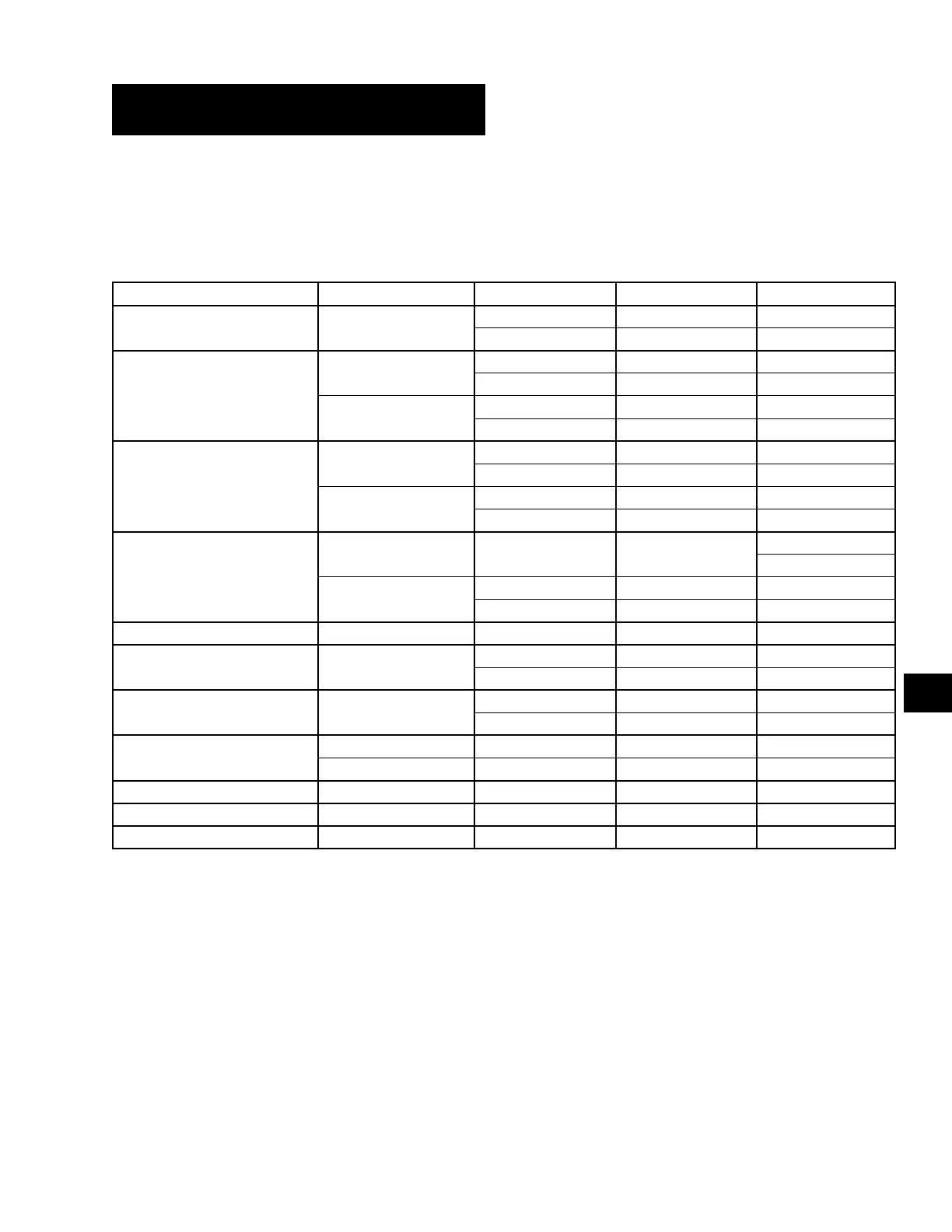
TABLE 16 - PROGRAM KEY LIMITS AND DEFAULT
PROGRAM VALUE MODE LOW LIMIT HIGH LIMIT DEFAULT
Discharge Pressure Cutout –
325 PSIG 575 PSIG 570 PSIG
22.4 BARG 39.6 BARG 39.3 BARG
Suction Pressure Cutout
Water Cooling
80.0 PSIG 120.0 PSIG 80.0 PSIG
5.52 BARG 8.27 BARG 5.52 BARG
Glycol Cooling
42.0 BARG 70.0 PSIG 44.0 PSIG
2.9 BARG 4.83 BARG 3.03 BARG
Low Ambient Temp. Cutout
Standard Ambient
25.0°F 60.0°F 25.0°F
-3.9°C 15.6°C -3.9°C
Low Ambient
0°F 60.0°F 25.0°F
-17.8°C 15.6°C -3.9°C
Leaving Chilled Liquid Temp.
Cutout
Water Cooling – –
36°F
2.2°C
Glycol Cooling
-1.0°F 36.0°F 36.0°F
-18.3°C 2.2°C 2.2°C
Anti-Recycle Timer – 300 SEC. 600 SEC. 600 SEC.
Fan Control On Pressure –
360 PSIG 485 PSIG 385 PSIG
24.8 BARG 33.4 BARG 26.5 BARG
Fan Differential Off Pressure –
80 PSID 160 PSID* 125 PSID
5.51 BARD 11.03 BARD 8.62 BARD
Total Number Of Compressors
Single System 2 3 3
Dual System 4 6 6
Number Of Fans Per System 2 4 3
Unit/System Trip Volts Current Feedback 0.5 Voltsd 4.5 Volts 2.5 Volts
Remote Unit ID – 0 7 0
* The minimum discharge pressure allowed is 235 PSIG. The Fan Differential Off Pressure High Limit will be lowered (reduced) to prevent go-
ing below 235 PSIG based on where the fan control On Pressure is programmed.
 Loading...


