JOHNSON CONTROLS
90
FORM 150.67-NM2
ISSUE DATE: 01/31/2019
SECTION 5 – TECHNICAL DATA
NOTE:
Placement on a level surface of free of obstructions (including snow, for winter operation) or air circulation ensures rated performance, reliable
operation, and ease of maintenance. Site restrictions may compromise minimum clearances indicated below, resulting in unpredictable airow
patterns and possible diminished performance. YORK’s unit controls will optimize operation without nuisance high-pressure safety cutouts;
however, the system designer must consider potential performance degradation. Recommended minimum clearances: front to wall – 2m;
rear to wall – 2m; cooler end to wall – 1.2m; coil end to wall – 2m; top – no obstructions allowed; distance between adjacent units – 3m.
No more than one adjacent wall may be higher than the unit. 1" nominal deection isolators (not shown) will increase overall unit height by
152mm.
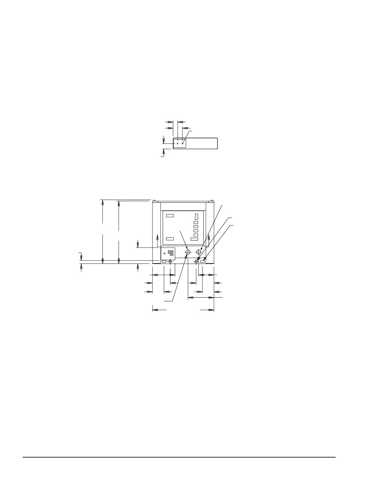
NOTE: All dimensions are in mm unless specied otherwise.
DIMENSIONS – YCAL0022 (SI)
LEFT END
171
82
100
BOTTOM OF PANEL
22 TYP.
VIEW B-B
POWER: SINGLE POINT SUPPLY WITH TERMINAL BLOCK
1170
1149
295
51 DIA
(2) 76 X 38
RIGGING HOLES
BOTH ENDS
1126
BASE WIDTH
477
280
TO ACCESS PANEL 412
211
325
211
325
B
B
58
51 VICTAULIC CONN
(typ)
IN
OUT
FIGURE 32 - DIMENSIONS - YCAL0022 (SI)
 Loading...


