JOHNSON CONTROLS
181
SECTION 9 – SERVICE AND TROUBLESHOOTING
FORM 150.67-NM2
ISSUE DATE: 01/31/2019
9
CHECKING INPUTS AND OUTPUTS
Digital Inputs
Refer to the unit wiring diagram. All digital inputs are
connected to J13-1 of the I/O board. The term “digital”
refers to two states – either on or off. As an example,
when the flow switch is closed, 30 volts DC will be ap-
plied to J13, pin 5 (J13-5) of the I/O board. If the flow
switch is open, 0 volts DC will then be present at J13-5.
Pin 1 of J13 is an unregulated 30VDC source used to
supply the DC voltage to the various user contacts,
unit switch, flow switch, etc. This DC source is fac-
tory wired to CTB1, terminal 13. Any switch or con-
tact used as a digital input would be connected to this
terminal, with the other end connecting to its respec-
tive digital input on the microboard. Any time a switch
or contact is closed, 30VDC would be applied to that
particular digital input. Any time a switch or contact is
open, 0VDC would be applied to that particular digital
input.
Typically, voltages of 24 – 36VDC could be measured
for the DC voltage on the digital inputs. This voltage is
in reference to ground. The unit case should be suffi-
cient as a reference point when measuring digital input
voltages.
Analog Inputs – Temperature
Refer to the unit wiring diagram. Temperature inputs
are connected to the microboard on plug J6. These ana-
log inputs represent varying dc signals corresponding
to varying temperatures. All voltages are in reference
to the unit case (ground). Following are the connec-
tions for the temperature sensing inputs:
Outside Air Sensor
J6-6 = +5VDC regulated supply to sensor.
J6-9 = VDC input signal to the microboard.
See Table 29 for voltage readings that corre-
spond to specific outdoor temperatures.
J6-3 = drain (shield connection = 0VDC) Return
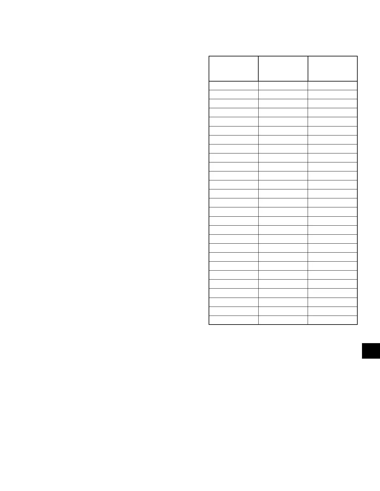
TABLE 34 - OUTDOOR AIR SENSOR
TEMPERATURE/VOLTAGE/
CORRELATION
TEMP °F
VOLTAGE
(SIGNAL INPUT
TO RETURN)
TEMP °C
0 0.7 -18
5 0.8 -15
10 0.9 -12
15 1.0 -9
20 1.1 -7
25 1.2 -4
30 1.4 -1
35 1.5 2
40 1.7 4
45 1.8 7
50 2.0 10
55 2.2 13
60 2.3 16
65 2.5 18
70 2.6 21
75 2.8 24
80 2.9 27
85 3.1 29
90 3.2 32
95 3.4 35
100 3.5 38
105 3.6 41
110 3.7 43
115 3.8 46
120 3.9 49
125 4.0 52
130 4.1 54
 Loading...


