JOHNSON CONTROLS
165
SECTION 8 – UNIT OPERATION
FORM 150.67-NM2
ISSUE DATE: 01/31/2019
8
YCAL0019 – 0033 LOW AMBIENT FAN
CONTROL OPTION
General
The low ambient option consists of a single phase Vari-
able Frequency Drive (VFD) that controls the speed of
the first fan (Fan 1) in the fan staging sequence. The
VFD is located in the control panel. An example of the
VFD location is shown in Figure 45 on page 165.
FIGURE 45 - TYPICAL VFD LOCATION
50093b
VFD
The VFD will control fan speed based on the liquid
temperature of the system. As liquid line temperature
rises and falls, the fan speed will operate between min-
imum and full speed RPM.
As liquid temperature rises, the VFD will ramp the
speed of the fan from a minimum speed of about 200
Hz to maximum RPM while attempting to control liq-
uid line temperature between 65-75° F. If the liquid
temperature is below 65-75° F, the VFD will shut off
the motor even though the VFD is powered by 7M.
The VFD control signal is sent from a liquid tempera-
ture sensor connected to a condenser coil return bend.
The sensor is connected to S1 and COM terminals of
the VFD in the control panel. The sensor must always
be insulated. The location of the sensor is shown in
Figure 46 on page 165.
BULB
FIGURE 46 - LIQUID LINE SENSING BULB
LOCATION
50094
The VFD will not only control fan speed in low ambi-
ent conditions, but in all ambients based on the liquid
line temperatute. Speed control of the fan will occur
whenever the liquid line solenoid is energized.
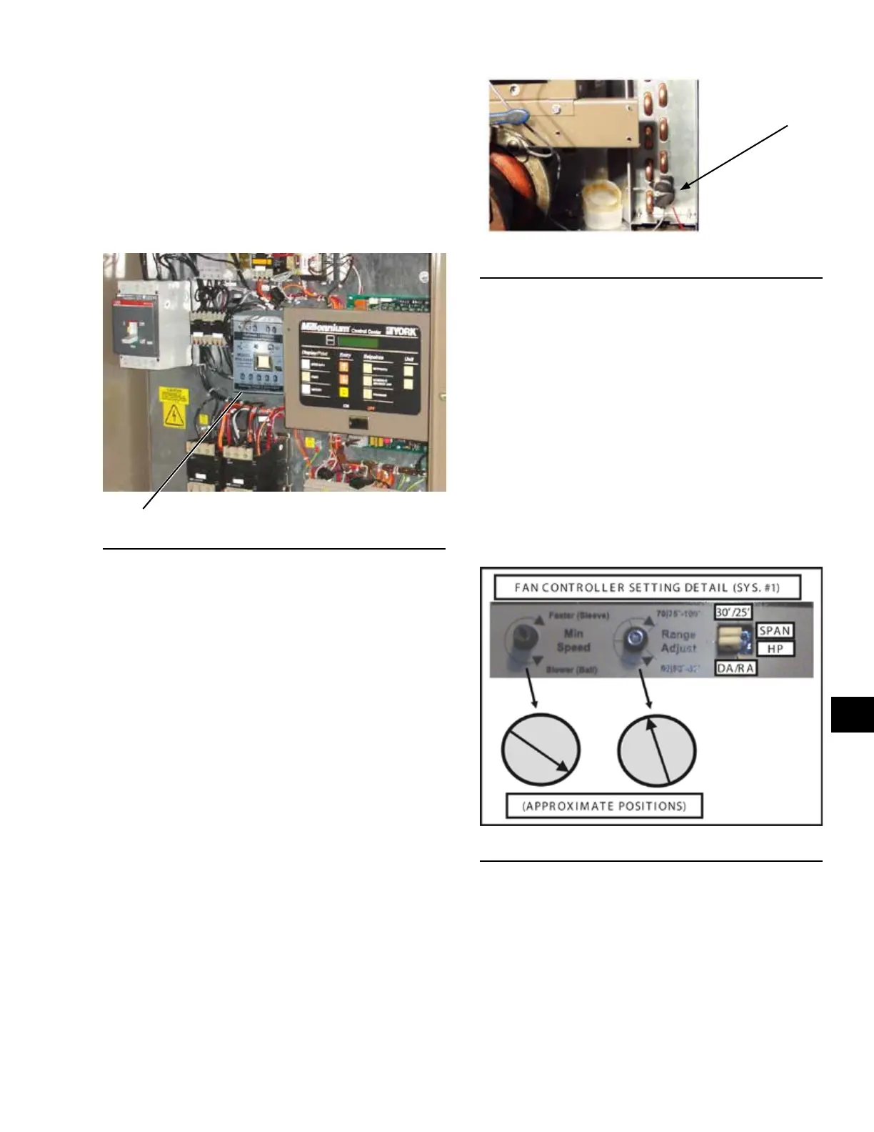
Potentiometer Configuration
The VFD is pre-configured from the factory prior to
shipping and should be ready for operation when the
chiller arrives on site. Potentiometers allow adjustment
of the minimum speed and for selection of the tempera-
ture control range. A quick check of the potentiometer
setting is recommended. The potentiometer settings
should be in the position shown in Figure 47 on page
165.
FIGURE 47 - POTENTIOMETER SETTINGS
50095
 Loading...


