JOHNSON CONTROLS
29
SECTION 3 - HANDLING, STORAGE, INSTALLATION AND REASSEMBLY
FORM 201.30-ICOM1 (519)
ISSUE DATE: 05/22/2019
3
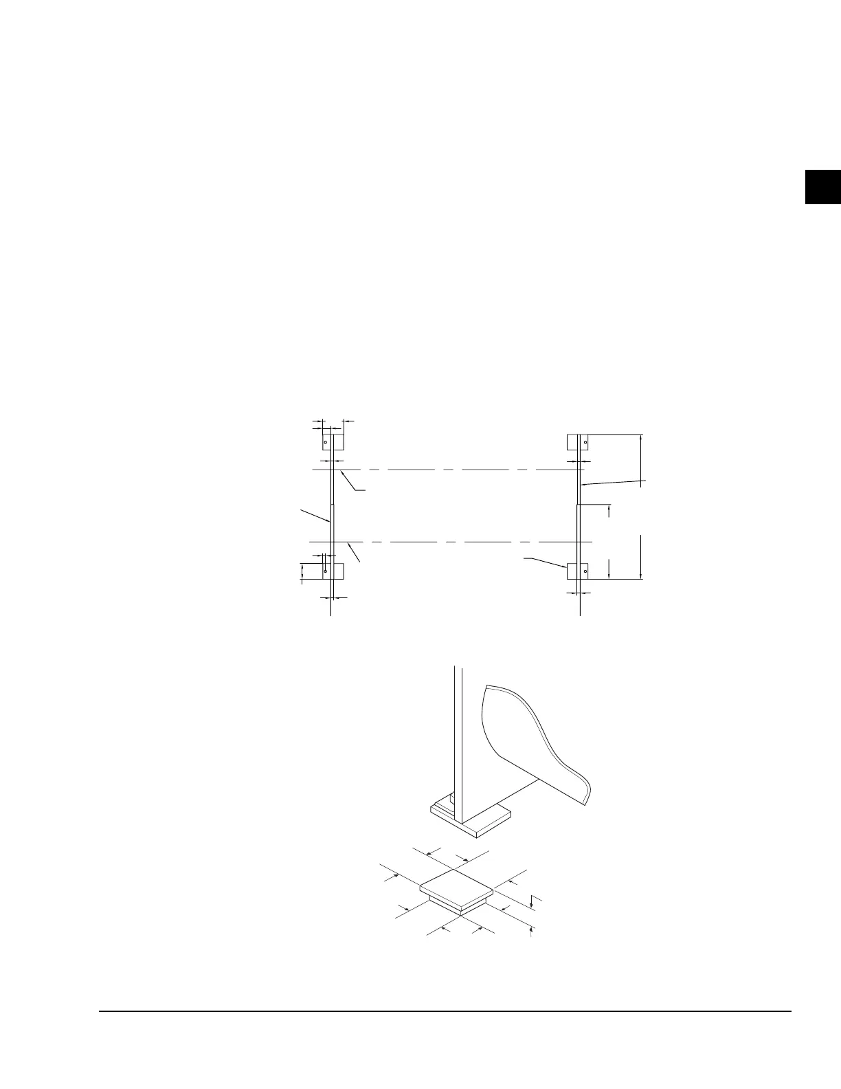
INSTALLING ELASTOMERIC VIBRATION
ISOLATOR PADS
Locate the elastomeric vibration isolator pads as shown
in Figure 9 on page 29 After placing the isolator
pads into position on the floor, lower the unit onto the
pads. Make sure the pads are even with the edges of the
mounting feet. When the unit is in place, check that the
chiller is level, longitudinally and transversely.
Checking Unit Alignment
Check the longitudinal alignment by placing a level on
the top center of the evaporator shell under the com-
pressor/motor assembly. Check the transverse align-
ment by placing a level on top of the shell end sheets at
each end of the unit.
The unit should be level within 0.25 in. (6 mm) from
one end to the other end, and from front to the rear. If
the chiller is not level within the amount specified, lift
it and place as many shims as needed between the iso-
lation pad and the end sheets.
Checking the Isolator Pad Deflection
Check all isolator pads for the proper deflection, which
is approximately 0.15 in. (4 mm). If an isolator pad is
under-deflected, place the shims between the unit end
sheet and the top of the pad to equally deflect all pads.
8” (203)
3” (76)
1” (26)
1-1/4” (32)
6” (152)
1” (25.4)
55-5/8”
(1413)
28-7/16”
(729)
CONDENSER
CENTERLINE
EVAPORATOR
CENTERLINE
SUPPORT
FOOT
END SHEET
END SHEET
1-1/4” (32)
1” (26)
ELASTOMERIC ISOLATOR
5.5 in (140 mm)
4.5 in
(114 mm)
4.5 in
(114 mm)
1.125 in
(29 mm)
5.5 in (140 mm)
END SHEET
SHELL
LD16425b
FIGURE 9 - ELASTOMERIC VIBRATION ISOLATOR PAD MOUNTS (STANDARD) - INCHES (MM)

 Loading...


