JOHNSON CONTROLS
31
SECTION 3 - HANDLING, STORAGE, INSTALLATION AND REASSEMBLY
FORM 201.30-ICOM1 (519)
ISSUE DATE: 05/22/2019
3
FORM 7 REASSEMBLY
The following is a recommended procedure used to re-
assemble the chiller.
1. Determine the nal location. Verify that the nal
location meets all of the minimum required clear-
ances. Refer to Figure 8 on page 28.
2. Rig the evaporator and place in the nal location
(refer to Figure 11 on page 33).
3. Rig the condenser, place it next to the evaporator,
and bolt the condenser and evaporator together
(refer to Figure 12 on page 34).
4. Level the evaporator and condenser
(refer to Figure 12 on page 34).
5. Install the isolator pads or optional spring isola-
tors to the condenser and evaporator end sheets
(refer to on page 36).
6. Install the heat exchanger piping
(refer to Figure 15 on page 37).
7. Install the liquid injection and oil return piping
(refer to Figure 16 on page 38).
8. Install the driveline (compressor/motor) assembly
(refer to Figure 18 on page 39).
9. Install the economizer piping to the compressor
(refer to page 39).
10. Mount the oil separator
(refer to Figure 18 on page 36).
11. Install the oil separator discharge mufer piping
(refer to Figure 18 on page 36). (Only required
with Isolation Valve)
12. Install compressor oil piping
(refer to Figure 20 on page 42).
13. Install oil supply piping
(refer to Figure 21 on page 42).
14. Mount the VSD (refer to Figure 22 on page 44).
15. Connect the VSD cooling lines
(refer to Figure 24 on page 45).
16. Mount and connect the Control Panel
(refer to Figure 23 on page 45).
Additional Instructions for Form 7
Reassembly
1. When installing the refrigerant piping, refer to
Piping Joint Assembly on page 46.
2. For wiring connections, refer to Field Con-
nections and Control Wiring for YVWA Chiller
(201.30-PW2).
3. For torque procedure and specications, refer Ta-
ble 4 on page 32.
4. Evacuate and charge the unit with refrigerant, re-
fer to Refrigerant Charging on page 137.
5. Pressure leak test. Remain below the relief valve
lift pressure indicated on the valve tags, refer to
Checking System for Leaks on page 138.
6. Charge the oil separator with the proper type and
quantity of YORK oil, refer to Adding Compres-
sor Oil on page 134.
7. Remove shipping antifreeze from VSD cooling
system and replace with coolant, refer to Check-
ing VSD Coolant Level on page 144.
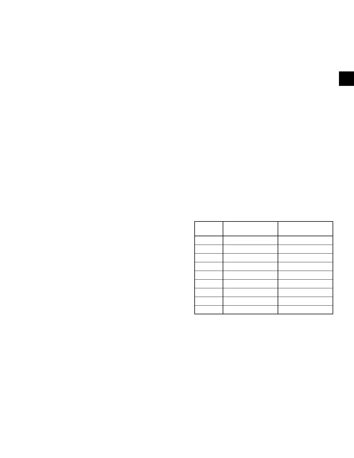
TABLE 3 - EVAPORATOR AND CONDENSER
WEIGHT (LB/KG)
SHELL
CODE
EVAPORATOR
(PIN 5,6)
CONDENSER
(PIN 7,8)
BB 2258/1024 1526 (692)
BC 2313/1049 1578 (716)
BD 2800/1270 1795 (814)
CB 2542/1153 1772 (804)
CC 2610/1184 1836 (833)
CD 2683/1217 1887 (856)
DB 2848/1292 2041 (926)
DC 2930/1329 2121 (926)
DD 3016/1368 2180 (989)
NOTE: The component weights listed in Table 3 on page 31
through 41 are approximate, and could vary from unit to unit.
Waterbox weights are NOT included.

 Loading...


