JOHNSON CONTROLS
56
FORM 201.30-ICOM1 (519)
ISSUE DATE: 05/22/2019
SECTION 3 - HANDLING, STORAGE, INSTALLATION AND REASSEMBLY
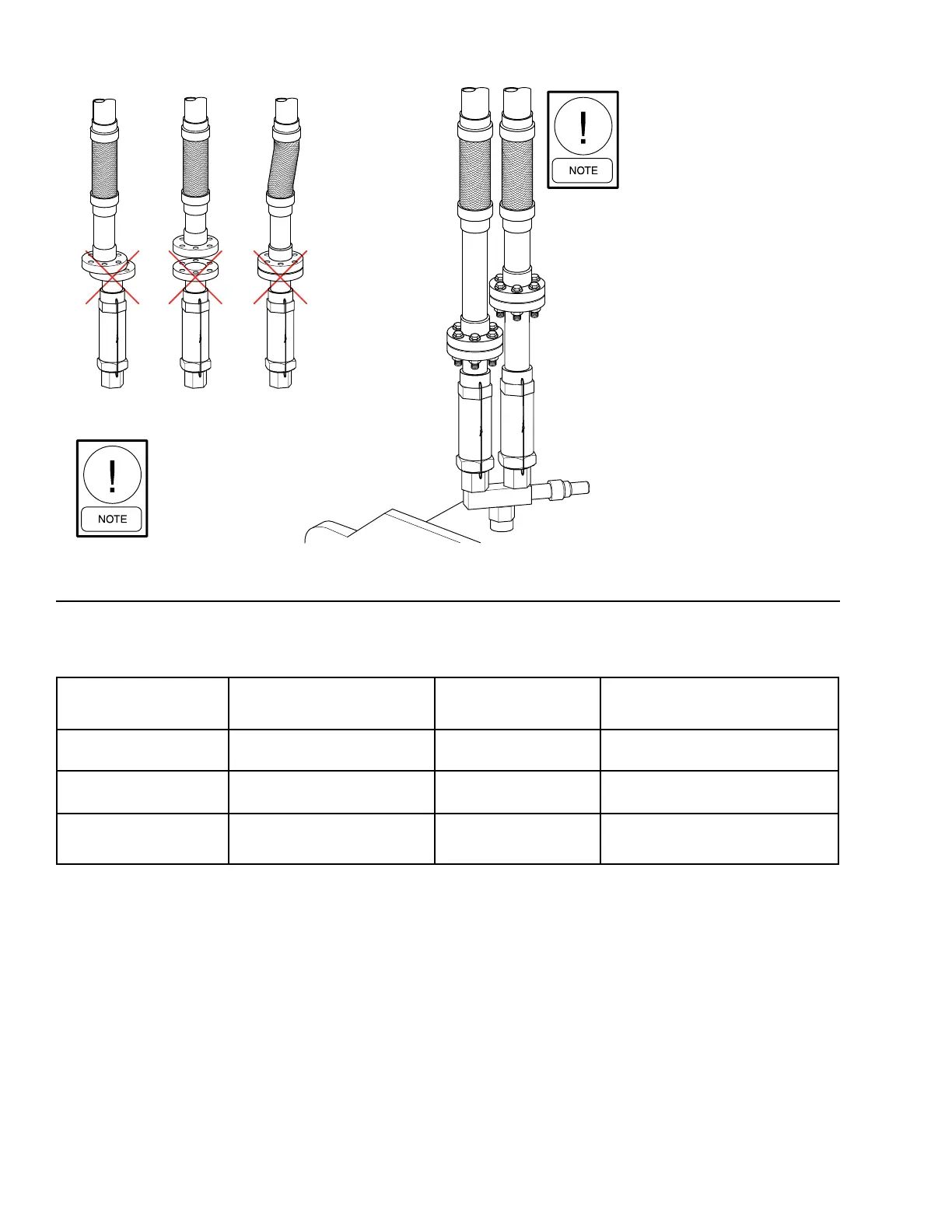
When installing relief piping there
must NOT be any piping strain.
Relief piping must be properly
aligned and supported to eliminate
any possible piping strain.
When installing relief piping an
ANSI flange or a piping union
must be used to make a
servicable piping connection.
Horizontal
Mis-aligned
Vertical
Offset
Compressed
LD16677
FIGURE 37 - TYPICAL COMPONENTS OF RELIEF PIPING
TABLE 19 - REFRIGERANT RELIEF CHARACTERISTICS (PER VALVE)
COMPONENT
DESIGN PRESSURE PSIG
(BAR)
AIR FLOW CAPACITY
LBS/MIN (KG/SEC)
OUTLET CONNECTION
EVAPORATOR
235
(16.2)
55.9 (0.423) 1” NPTF
CONDENSER
235
(16.2)
55.9 (0.423) 1” NPTF
CONDENSER
(HEAT PUMP OPTION)
388
(26.8)
90.3 (0.681) 1” NPTF
NOTES:
1. Dual relief valve consists of one three-way shut-off valve and two single relief valves. The valve conguration will not allow both valves to be
shut off at the same time, and valves are sized such that each relief valve has sufcient discharge capacity when used alone, which permits
safe removal of either relief valve for repair or replacement, while maintaining vessel protection.
2. Above information is for presssure vessels designed in accordancce with ASME Boiler and Pressure Vessel Code.

 Loading...


