5.1.1 DC cable and brake resistor cable
5.1.1.1 Contacting the shielding of the DC cable on the ZArec4C 013
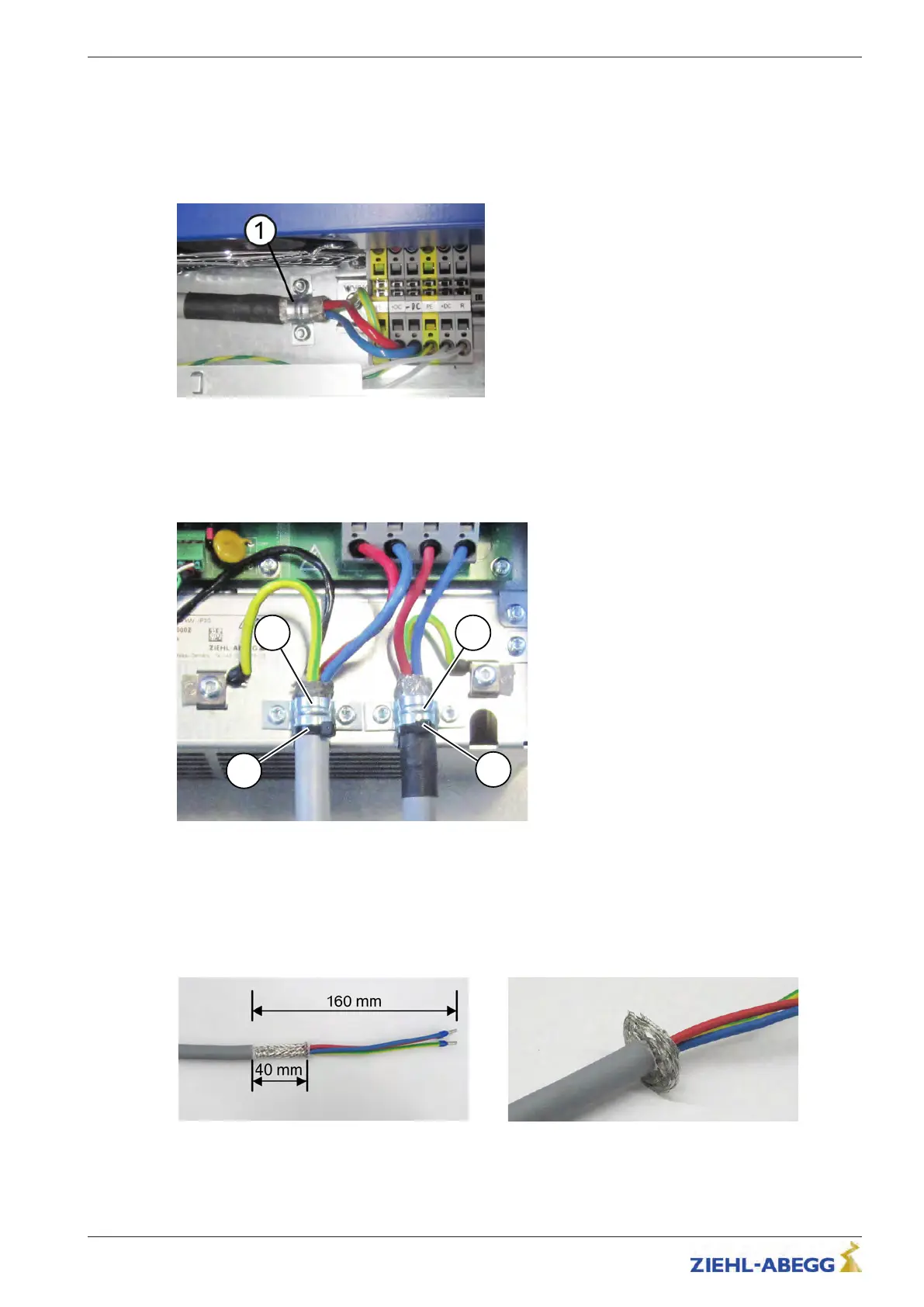
On the ZArec4C 013, the shielding of the DC cable must be connected to the earth potential with the
clip provided (see fig.).
1 Clip
5.1.1.2 Contacting the shielding of the DC cable and brake resistor cable on the ZArec4C 026/039
On the ZArec4C 026/039, the shieldings of the DC cable and brake resistor cable must be connected
to the earth potential with the clip provided (see fig.).
1 Clip
2 Cable tie for strain relief
5.1.1.3 Contacting the shielding of the DC cable on the ZETADYN 3C
1. Remove the insulation of the DC cable over a length of 160 mm.
2. Cut shielding braid to length up to 40 mm.
3. Arrange shielding braid as shown in the figure.
The cable shield for the DC cable must be placed on
the ZETADYN 3C with the EMC cable screw
glands (see the operating instructions of the ZETADYN 3C).
Original operating instructions
ZArec4C Electrical installation
R-TBA14_03-GB 1817 Index 007 Part.-No. 00163436-GB
1
7/64
 Loading...