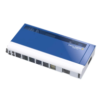
In the case of the ZArec4C 026/039, the PE conductor is connected via the clip next to the X-BR
connection terminal on the housing (see fig.).
1 Clip PE conductor connection ZArec4C 026/039
5.10 Connecting DC cable (ZArec4C 013: X2 / ZArec4C 026/029: X-DC)
CAUTION!
Warning!
An incorrect connection at the +DC and -DC terminals on the ZArec4C or the ZAdyn can destroy the
ZArec4C or the ZAdyn.
CAUTION!
Warning!
In devices of the ZETADYN 3C type only the connecting cables +DC (red) and R (blue) are connected
to the terminal X2!
If the ZArec4C is used in connection with devices of the ZETADYN 3C type, the blue wire must be
rewired from the connection terminal R to the connection terminal -DC on the internal ZETADYN 3BF!
5.10.1 Type of cable
•
Shielded cables must be used. The shieldings must be connected to the shield connection (clip)
next to the X2 or X-DC terminal.
•
It is recommended to use the pre-assembled connection cable LS-ZArec4C-xx-HX-xx-ZA3/4.
Type Cable cross section
ZAdyn 011-023 2,5 mm
2
6,0 mm
2
ZAdyn 032-074
5.10.2 Cable length
•
maximum line length: 5 m
•
When lines over >5 m are used, compliance with DIN EN 12015 (electromagnetic compatibility –
electrical interference) and DIN EN 12016 (electromagnetic compatibility – noise immunity) is no
longer guaranteed.
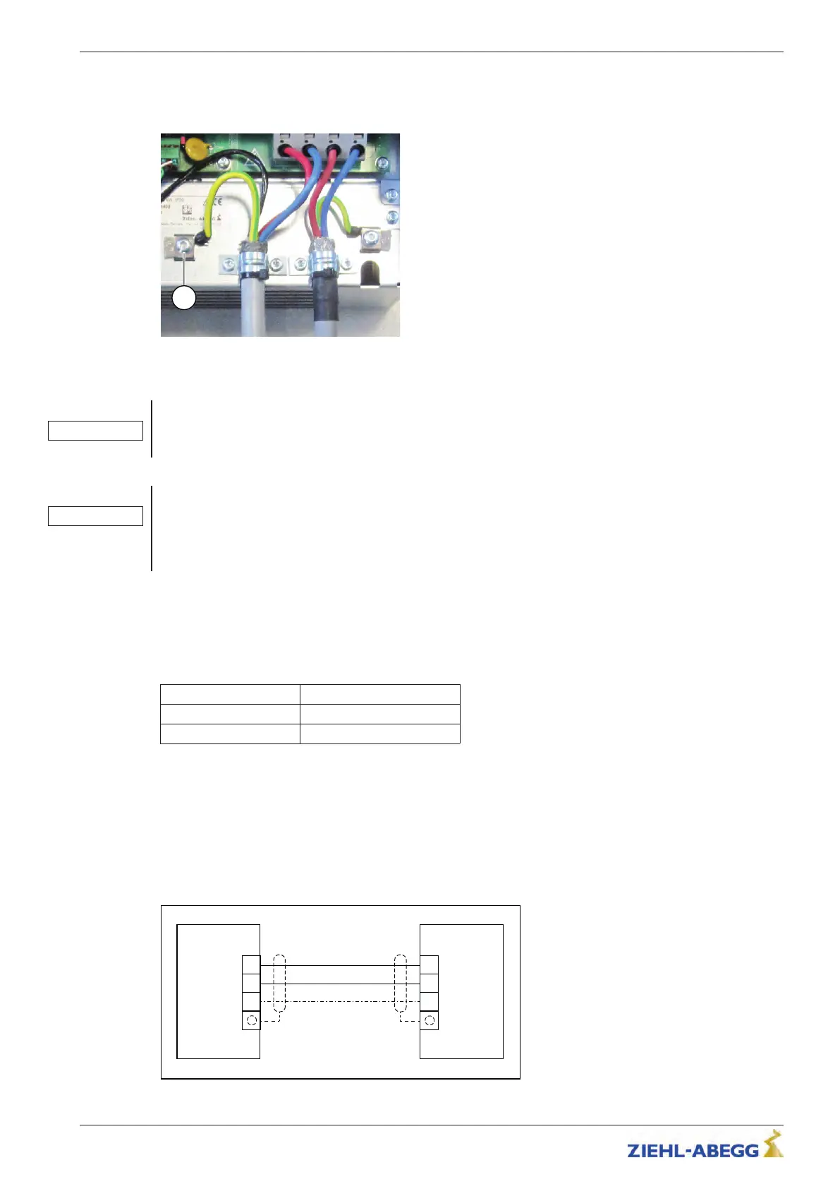
5.10.2.1 Connection
Connecting DC cable to frequency inverter type ZAdyn
/ ZETADYN
Original operating instructions
ZArec4C Electrical installation
R-TBA14_03-GB 1817 Index 007 Part.-No. 00163436-GB
2
9/64
 Loading...