194 Actual signals and parameters
COMM Fieldbus interface as the source for the fault reset signal, ie
Control word 0301 FB CMD WORD 1 bit 4 (with ABB drives
profile 5319 EFB PAR 19 bit 7). The Control word is sent by
the fieldbus controller through the embedded fieldbus
(Modbus) to the drive. For the Control word bits, see
sections DCU communication profile on page 307 and ABB
drives communication profile on page 302.
8
DI1(INV) Reset through inverted digital input DI1 (reset on the falling
edge of DI1) or from the control panel
-1
DI2(INV) See selection DI1(INV).-2
DI3(INV) See selection DI1(INV).-3
DI4(INV) See selection DI1(INV).-4
DI5(INV) See selection DI1(INV).-5
1605 USER PAR
SET CHG
Enables the change of the User parameter set through a
digital input. See parameter 9902 APPLIC MACRO. The
change is only allowed when the drive is stopped. During
the change, the drive does not start.
Note: Always save the User parameter set with parameter
9902 after changing any parameter setting, or reperforming
the motor identification. The last settings saved by the user
are loaded into use whenever the power is switched off and
on again or the parameter 9902 setting is changed. Any
unsaved changes are lost.
Note: The value of this parameter is not included in the
User parameter sets. A setting once made remains despite
User parameter set change.
Note: Selection of User parameter set 2 can be supervised
through relay outputs RO 1…4 and digital output DO. See
parameters 1401 RELAY OUTPUT 1 … 1403 RELAY
OUTPUT 3, 1410 RELAY OUTPUT 4 and 1805 DO
SIGNAL.
NOT SEL
NOT SEL User parameter set change is not possible through a digital
input. Parameter sets can be changed only from the control
panel.
0
DI1 User parameter set control through digital input DI1. Falling
edge of digital input DI1: User parameter set 1 is loaded into
use. Rising edge of digital input DI1: User parameter set 2 is
loaded into use.
1
DI2 See selection DI1.2
DI3 See selection DI1.3
DI4 See selection DI1.4
DI5 See selection DI1.5
DI1(INV) User parameter set control through inverted digital input
DI1. Falling edge of inverted digital input DI1: User
parameter set 2 is loaded into use. Rising edge of inverted
digital input DI1: User parameter set 1 is loaded into use.
-1
DI2(INV) See selection DI1(INV).-
2
DI3(INV) See selection DI1(INV).-3
DI4(INV) See selection DI1(INV).-4
DI5(INV) See selection DI1(INV).-5
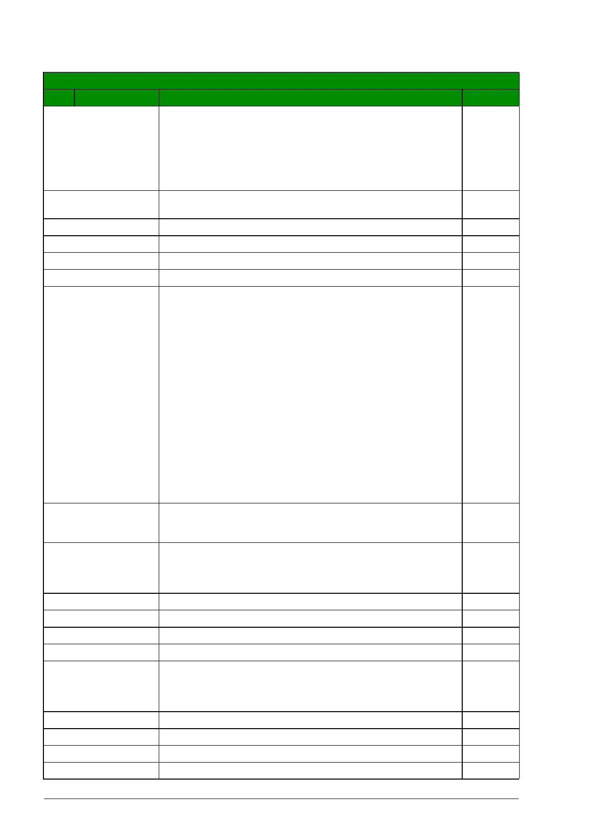
All parameters
No. Name/Value Description Def/FbEq

 Loading...


